
Headrest with energy dissipater for rear passenger

a rear passenger and headrest technology, applied in the direction of chairs, pedestrian/occupant safety arrangements, vehicular safety arrangements, etc., can solve the problems of time-consuming, limited design variations of prior art headrests, and added difficulty in predicting dynamic behavior and performan

Inactive Publication Date: 2011-04-26
FAURECIA AUTOMOTIVE SEATING LLC
View PDF16 Cites 7 Cited by
  • Summary
  • Abstract
  • Description
  • Claims
  • Application Information

AI Technical Summary

Benefits of technology

[0014]In accordance with another aspect of the first embodiment, there is disclosed a headrest wherein the post comprises a free end and, in said first pivot position, said free end contacts an interior surface of said first sleeve portion, and, in said second position, said free end contacts an interior surface of said second sleeve portion, thereby limiting said pivotal movement of the headrest in an opposed pivotal direction.

Problems solved by technology

Variations in the design of prior art headrests are restricted by the selection of alternative foams and material coverings.
There is also an added difficulty in predicting dynamic behavior and performance during the impact of a crash as those skilled in the art will appreciate when working with foam materials.
This process is time consuming, expensive and results in significant wasted materials.

Method used


Image

  • Headrest with energy dissipater for rear passenger
  • Headrest with energy dissipater for rear passenger
  • Headrest with energy dissipater for rear passenger

Examples


Embodiment Construction

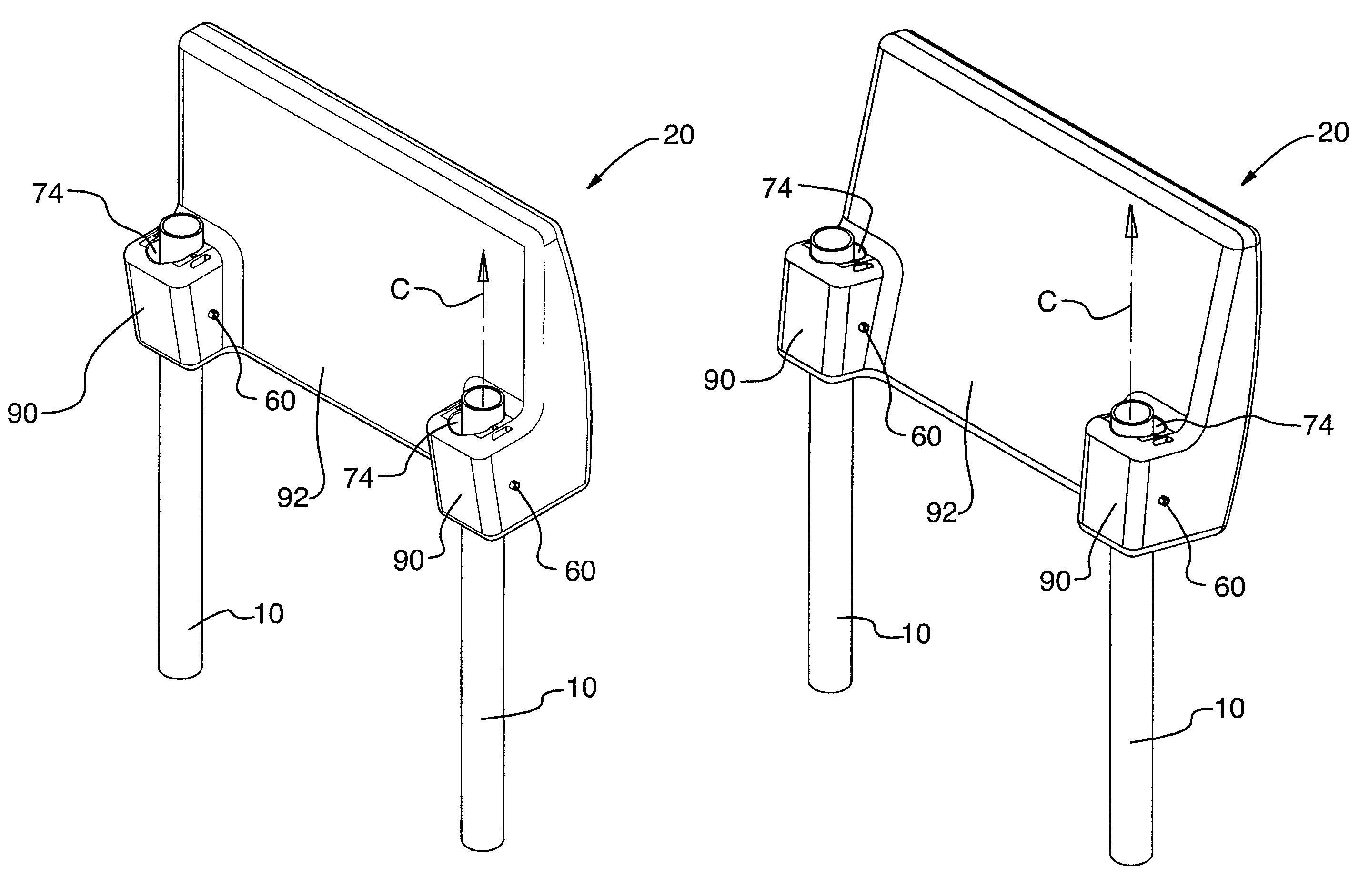
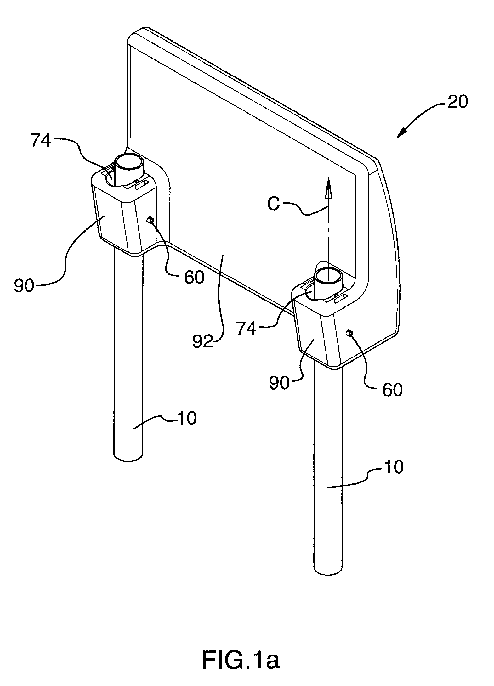
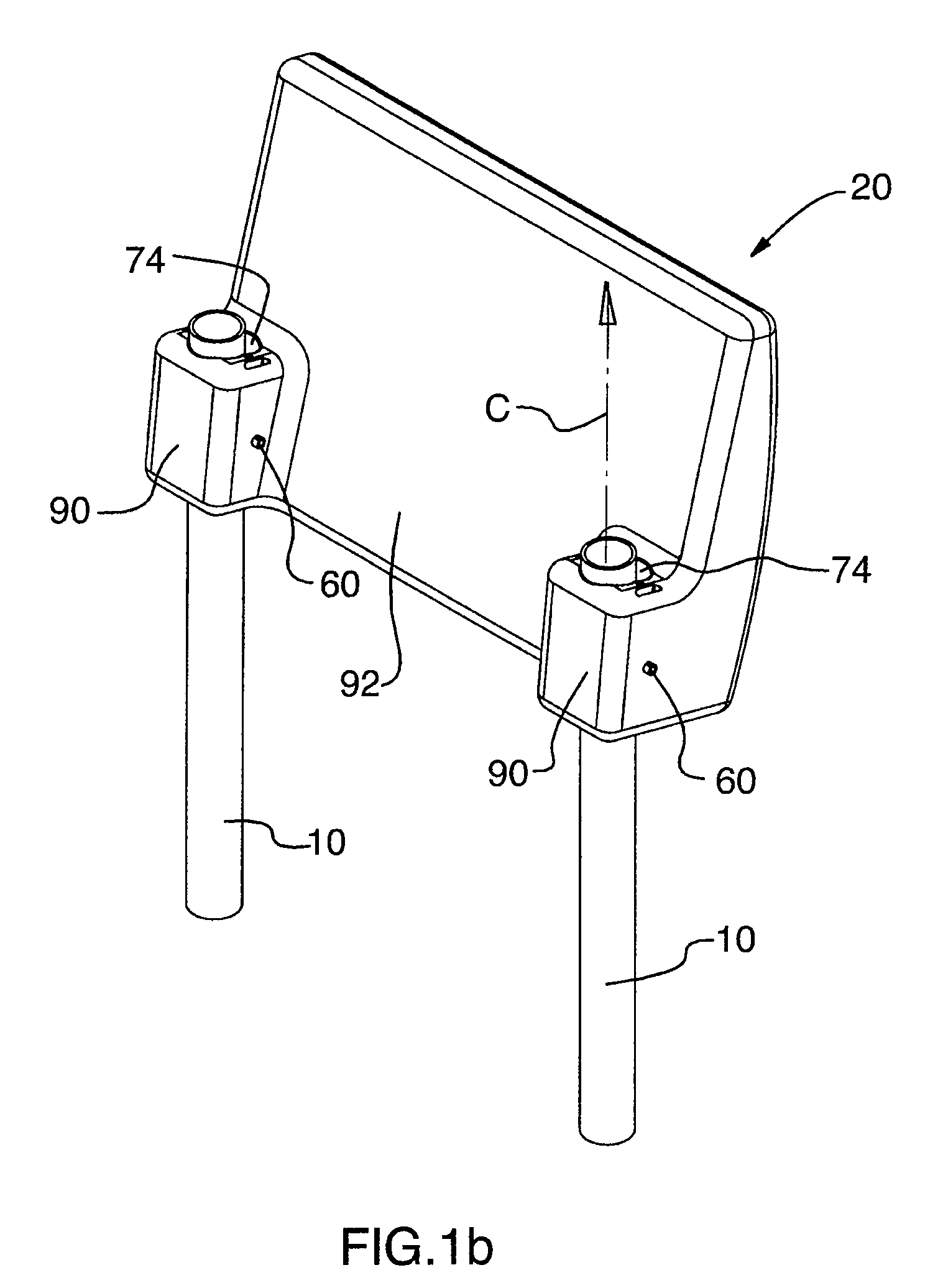
[0040]Referring now to FIGS. 1a-1c of the drawings, there is shown a headrest 20 according to a preferred embodiment of the present invention. Mounted on the backrest (not shown) of a vehicle seat is typically a pair of vertically extending cylindrical posts 10 upon which the headrest 20 is mounted. The descriptor “vertically” is used herein only in reference to a general direction from the backrest and is not meant as an absolute direction to limit the present invention. The headrest 20 includes one or more mounting sleeves 74 each adapted to surround a longitudinal portion or segment of a respective one of mounting posts 10. In the preferred embodiment illustrated, there are two mounting sleeves 74 for respective mounting on each post 10 in pivotal relation thereto, such that the headrest 20 can pivot, in a controlled manner, from a first pivot position, as shown in FIG. 1a, through an intermediate position, as shown in FIG. 1c, and on to a second pivot position, as shown in FIG. ...


PUM


Abstract

A headrest for mounting on one or more vertically extending posts positioned on the backrest of a vehicle seat, the headrest comprising one or more mounting sleeves positioned on the headrest and adapted to surround a portion of a respective one of said posts, pivot means extending between each mounting sleeve and the respective post to mount the mounting sleeve on the respective post in pivotal relation thereto about a pivot axis substantially transverse to the longitudinal axis of the post, each mounting sleeve being shaped and otherwise dimensioned on an internal surface to resist pivotal motion of the headrest between first and second positions below application of a directed threshold force to the headrest.

Description

FIELD OF THE INVENTION[0001]The present invention relates to the field of headrests and more specifically to, an automobile headrest having an energy dissipating function for a rear passenger impacting the back of the headrest.BACKGROUND OF THE INVENTION[0002]A front seat automobile headrest includes an energy dissipating function for an object colliding with the back of the front seat of the vehicle when the vehicle undergoes a deceleration caused by a crash or other impact. As a result of the deceleration, the object, typically a rear passenger, having forward momentum continues forward and collides with the back of the front seat. Generally, a seat belt is worn and the body of the passenger is restrained such that the rear passenger's head collides with the back of the headrest.[0003]In the prior art, the energy dissipating function is typically formed by the headrest including a foam core component having a soft material covering. The combination of the foam core and soft coveri...

Claims


Application Information

Patent Timeline
Patent Type & Authority Patents(United States)
IPC IPC(8): B60N2/42B60N2/427B60R21/055B60R22/28
CPCB60N2/4221B60N2/4885B60N2/4838B60N2/838B60N2/888
Inventor GOMES, LEONARDODUHAMEL, PHILIPPE
Owner FAURECIA AUTOMOTIVE SEATING LLC
Learn More