
Forward firing fragmentation warhead

a technology of fragmentation warheads and warheads, applied in the field of fragmentation warheads, can solve the problems of increasing the potential for collateral damage to friendly troops and the launch platform, the tolerance of aimpoint and detonation timing to engage and destroy the threat while minimizing collateral damage, and the threat is present collateral damage, so as to reduce collateral damage and the effect of reducing the threat lethal

Active Publication Date: 2011-04-26
RAYTHEON CO
View PDF37 Cites 3 Cited by
  • Summary
  • Abstract
  • Description
  • Claims
  • Application Information

AI Technical Summary

Benefits of technology

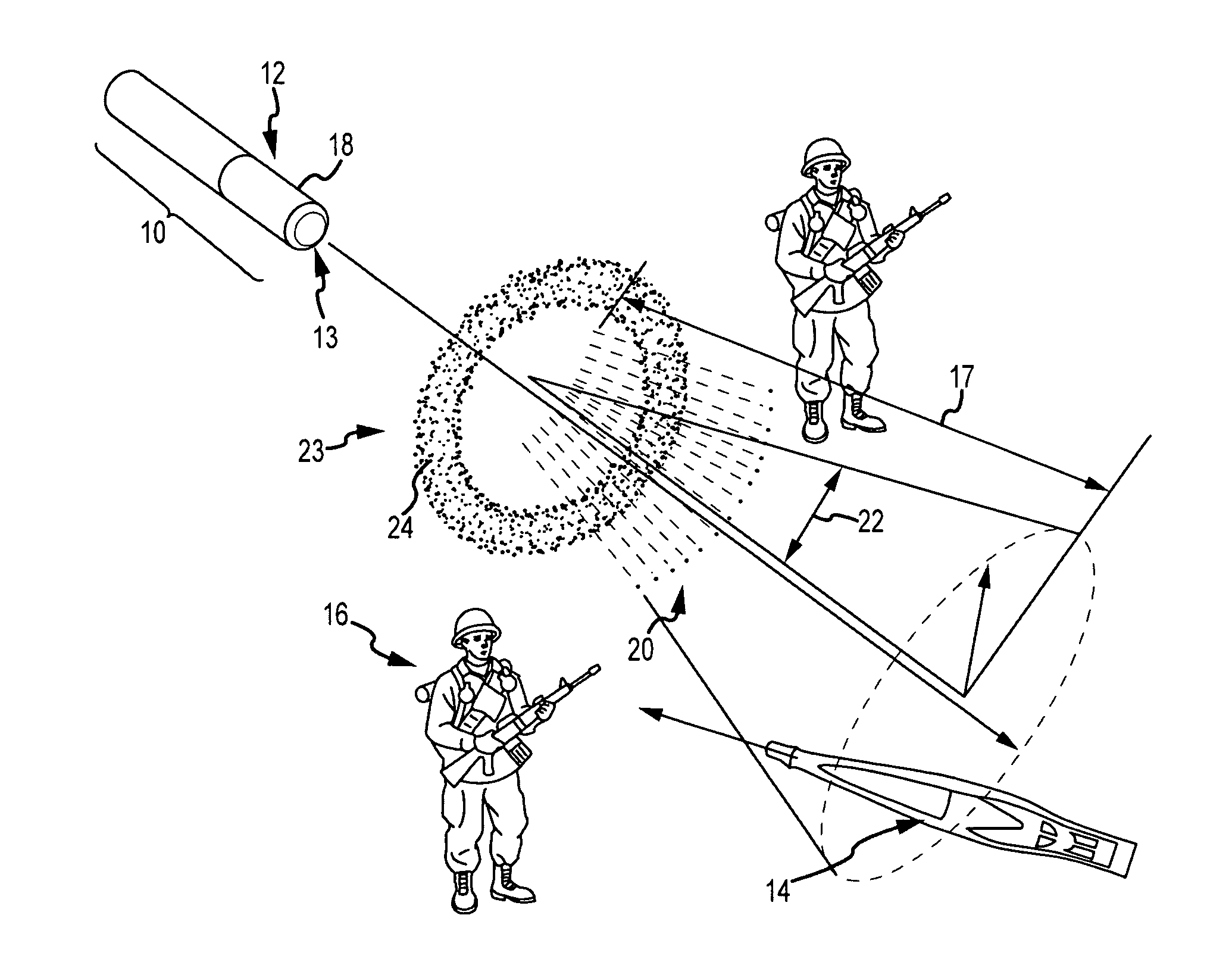
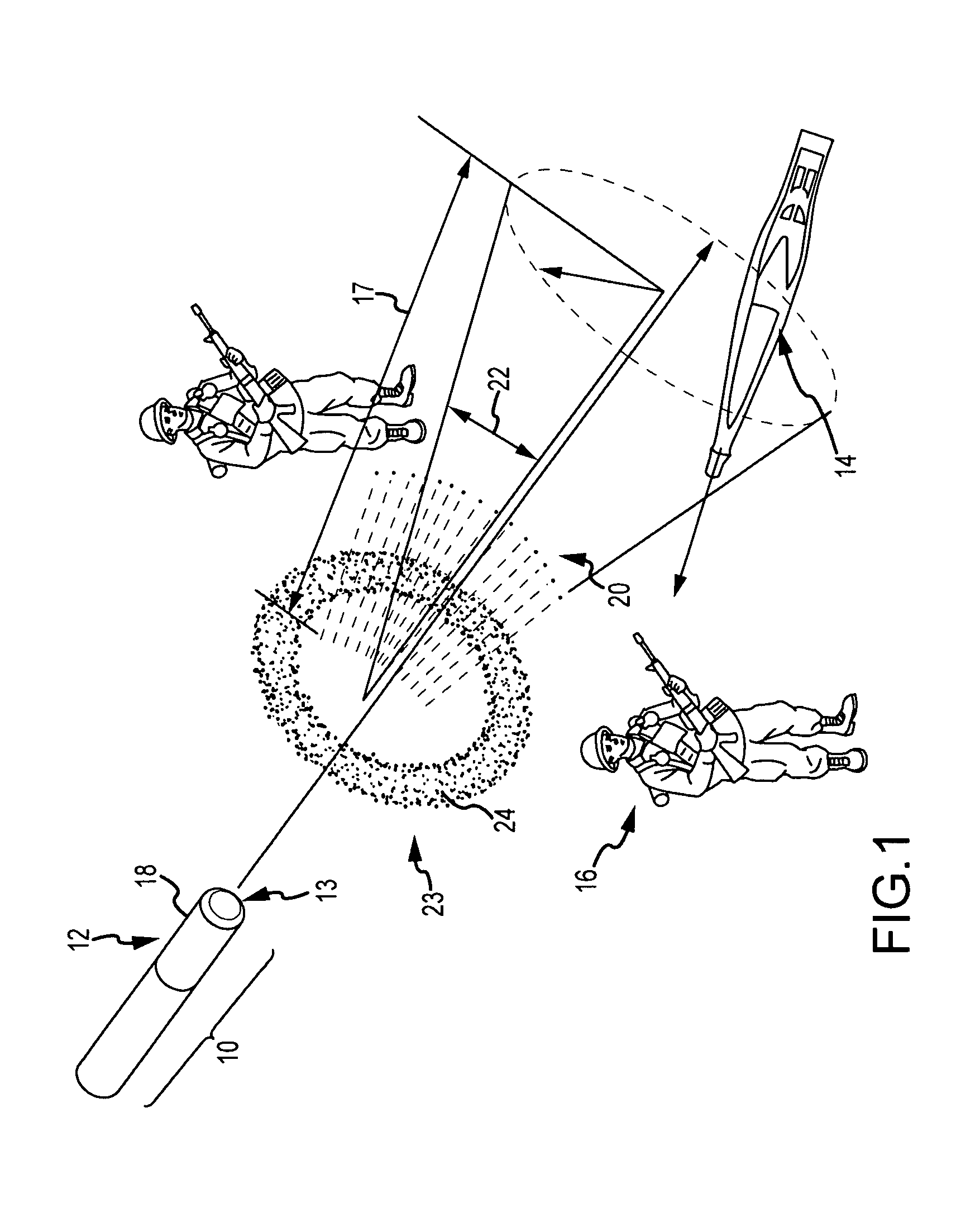
[0010]The present invention provides a forward firing fragmentation warhead that provides threat lethality and reduced collateral damage.
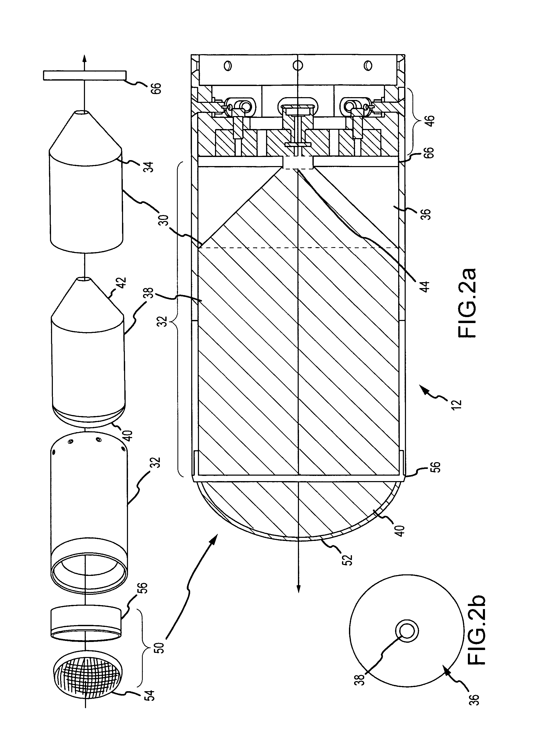
[0012]In another embodiment, the warhead includes an explosive containment structure inside a case. An explosive is placed in the containment structure and an initiator is placed aft of the explosive. Both the case and containment structure are formed of materials that are pulverized upon detonation of the explosive. A forward-firing fragmentation assembly is positioned forward of the explosive to expel fragments in a forward-firing pattern upon detonation of the explosive. The fragmentation assembly includes a dome-shaped layer of fragments that is at least approximately conformal with a dome-shaped forward end of the explosive. A pattern shaper may be inserted between the fragmentation layer and the explosive, otherwise they would be conformal. The dome-shape is approximately matched to the shape of the front of the pressure wave that reaches the fragmentation assembly upon detonation. This increases fragment velocity and expels the fragments in a more uniform pattern.
[0013]In another embodiment, the warhead includes an explosive containment structure inside a case. The containment structure has a forward section with a diameter conformal with the forward section of the case and has a tapered aft section that tapers to a reduced diameter to define a tapered void space between the case and the containment structure. An explosive is placed in the containment structure and an initiator is placed aft of the explosive. Both the case and containment structure are formed of materials that are pulverized upon detonation of the explosive. A forward-firing fragmentation assembly is positioned forward of the explosive to expel fragments in a forward-firing pattern upon detonation of the explosive. Upon detonation a pressure wave propagates forward through the tapered explosive to the diameter of the case. The taper may be optimized to match the expansion of the pressure wave thereby maximizing the void space without reducing the total explosive energy imparted to the fragmentation assembly. The elimination of explosive reduces both the cost and weight of the warhead.

Problems solved by technology

Although lethal, the radial distribution of the fragments also presents the potential for collateral damage to friendly troops and the launch platform.
In other words, the mass efficiency is the ratio of the total mass less the interstitial mass that was consumed during the launch process (therefore ineffective against the intended target) to the total mass.
As a result, the warhead has a maximum lethality confined to a very narrow angle and expels a certain amount of lethal fragments outside the desired target area that may cause collateral damage.
As a result, the aimpoint and detonation timing tolerances to engage and destroy the threat while minimizing collateral damage are tight.
Detonation of the steel case increases the potential for collateral damage to friendly troops and the launch platform.

Method used


Image

  • Forward firing fragmentation warhead
  • Forward firing fragmentation warhead
  • Forward firing fragmentation warhead

Examples


Embodiment Construction

[0019]The present invention describes a high-lethality low collateral damage forward firing fragmentation warhead. The reduction in collateral damage is accomplished by forming the case of a material that is pulverized upon detonation of the explosive. As a result, the lethality radius of the pulverized case fragments is no greater than that of the gas blast, thus reducing potential collateral damage. Warhead lethality may be improved by forming the fragmentation layer and explosive with a dome-shape that approximately matches the shape of the front of the pressure wave. This increases fragment velocity and improves the uniformity of the fragment distribution over the forward-firing pattern. A variable-thickness pattern shaper may be placed between the fragmentation layer and explosive to provide additional shaping of the forward-firing pattern. Warhead weight and cost can be reduced by eliminating explosive at the aft end of the warhead that does not contribute to the total energy ...


PUM


Abstract

A forward firing fragmentation warhead is constructed with casing materials that are pulverized upon detonation of the explosive. As a result, the lethality radius of the pulverized case fragments is no greater than that of the gas blast, thus reducing potential collateral damage. Warhead lethality may be improved by forming the fragmentation layer and explosive with dome-shapes that approximately match the shape of the advancing pressure wave. This increases fragment velocity and improves the uniformity of the fragment distribution over the forward-firing pattern. A variable-thickness pattern shaper may be placed between the fragmentation layer and explosive to provide additional shaping of the forward-firing pattern. Warhead weight and cost can be reduced by eliminating explosive at the aft end of the warhead that does not contribute to the total energy imparted to the fragments. More specifically, the aft section of the explosive and explosive containment structure may be tapered to approximately match the expansion of the pressure wave from the single-point aft detonation.

Description

CROSS-REFERENCE TO RELATED APPLICATIONS[0001]This application claims benefit of priority under 35 U.S.C. 120 as a continuation-in-part of co-pending U.S. Utility application Ser. No. 12 / 123,158 entitled “High-Lethality Low Collateral Damage Fragmentation Warhead” and filed on May 19, 2008, the entire contents of which are incorporated by reference.BACKGROUND OF THE INVENTION[0002]1. Field of the Invention[0003]This invention relates to fragmentation warheads and in particular to a forward firing fragmentation warhead that expels a mass of fragments in a forward-firing pattern.[0004]2. Description of the Related Art[0005]Fragmentation warheads expel metal fragments upon detonation of an explosive. Fragmentation warheads are used as offensive weapons or as countermeasures to anti-personnel or anti-property weapons such as rocket-propelled grenades. The warheads may be launched from ground, sea or airborne platforms. A typical warhead includes an explosive inside a steel case. A booste...

Claims


Application Information

Patent Timeline
Patent Type & Authority Patents(United States)
IPC IPC(8): F42B12/32
CPCF42B1/024F42B12/32F42B12/10F42B1/028
Inventor DUPONT, JAMES H.KIM, HENRI Y.WALTER, TRAVIS P.CHRISTANSON, KIM L.
Owner RAYTHEON CO
Learn More