
Patient support device and method for use

a technology for supporting devices and patients, applied in the field of patient support devices and methods for use, can solve the problems of limited use of cat and mri for intraoperative imaging and interventional radiology, poor soft tissue contrast, etc., and achieve the effects of reducing time and effort, reducing weight, and quick positioning

Inactive Publication Date: 2011-04-12
KINMON TRIP
View PDF25 Cites 1 Cited by
  • Summary
  • Abstract
  • Description
  • Claims
  • Application Information

AI Technical Summary

Benefits of technology

The support device reduces patient movement and muscle tension, improving imaging quality, minimizing the need for re-examinations, and reducing the risk of complications by providing stable support during medical procedures.

Problems solved by technology

CAT is known to be particularly useful for volumetric imaging but also suffers from poor soft tissue contrast, while MRI offers multi-planar imaging with superior soft tissue contrast.
The use of CAT and MRI for intraoperative imaging and interventional radiology (e.g., performing minimally invasive, targeted treatments using imaging for guidance) previously has been limited because of the substantial challenges posed by the geometry and overall size of the imaging equipment.
The donut-shaped, ring-type gantries of traditional CAT and MRI equipment, for example, are not easily accommodated, and can cause or suffer from various deleterious effects due to interactions with other equipment.
The head supports, as disclosed in Day, are generally expensive, directly attached to the support table, and complicated to use.

Method used


Image

  • Patient support device and method for use
  • Patient support device and method for use
  • Patient support device and method for use

Examples


Embodiment Construction

[0027]Embodiments of the presently disclosed patient support device will now be described in detail with reference to the drawing figures, wherein like reference numerals identify identical or substantially similar parts throughout the several views. In the drawings and in the description which follows, the term “proximal”, as is traditional, will refer to the end of the patient support device which is closest to the operator or patient, while the term “distal” will refer to the end of the device which is farthest from the operator or patient.

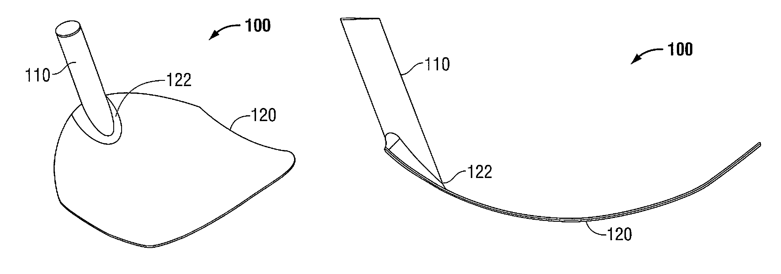
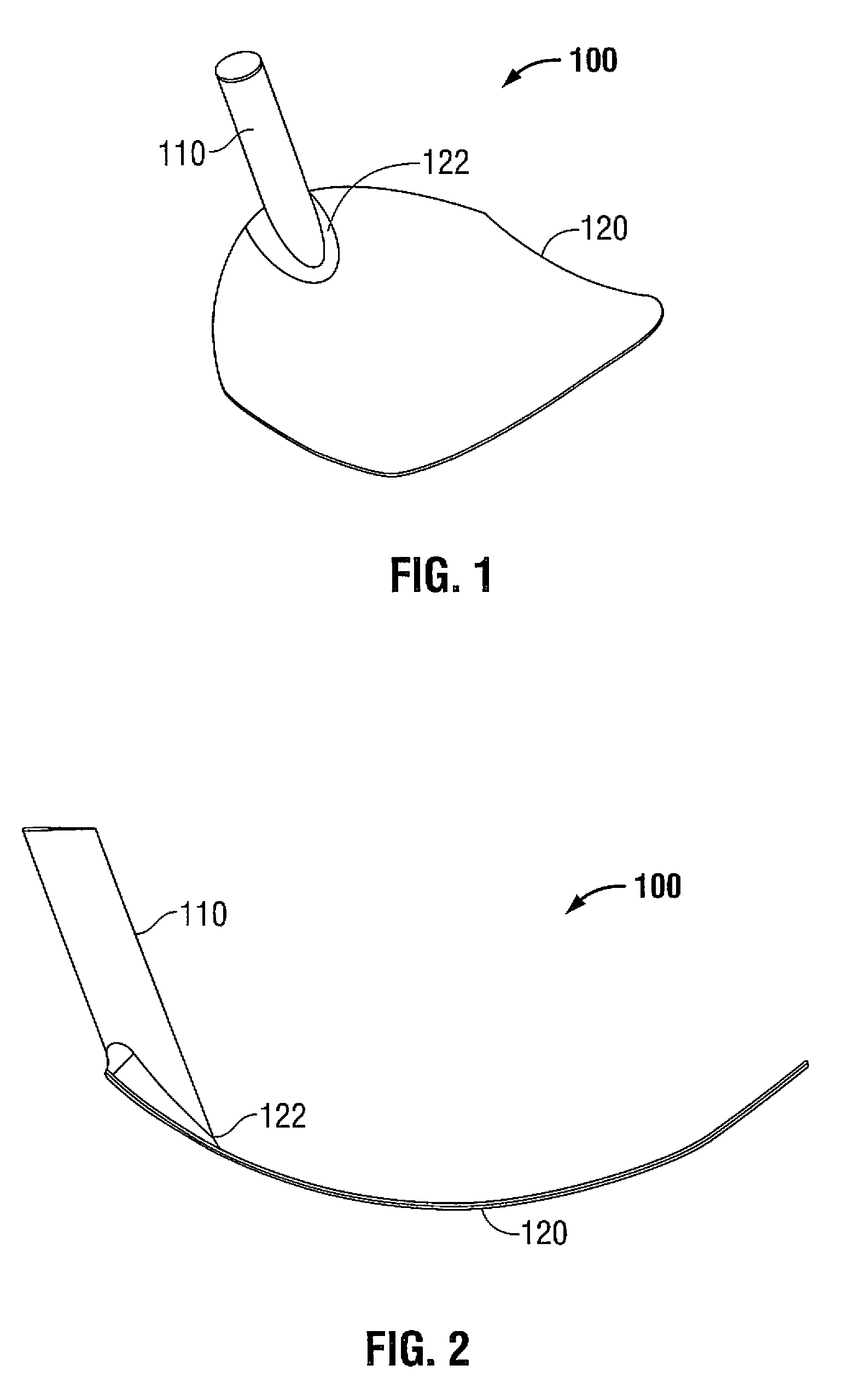
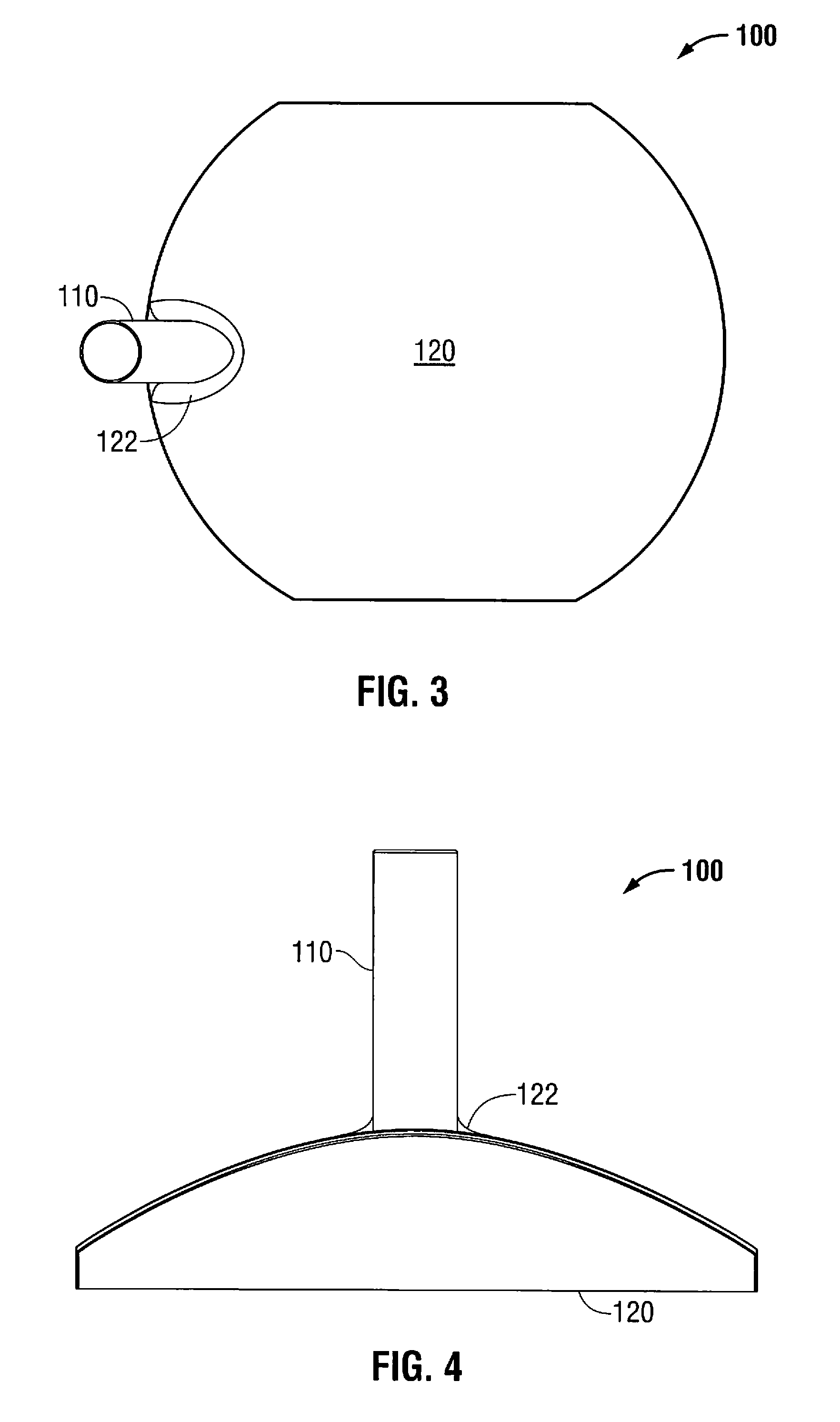
[0028]Referring now to the drawings, FIGS. 1-5 illustrate a patient support device that is generally designated as 100. The patient support device 100 includes a base 120 and a handle 110. The base 120 has a structural composition that allows it to conform with different contoured and uncontoured surfaces, including the patient's anatomy and / or diagnostic support tables. A fillet 122 provides a transition between the base 120 and the handle 110...


PUM


Abstract

A patient support device for positioning the anatomy of a patient during a medical procedure includes a base and a handle. The base is supported on the top of a patient support table. The handle protrudes from a proximal side of the base. Both the base and the handle are made from a biocompatible, radiolucent material that is capable of being used during a radiographic procedure.

Description

CROSS-REFERENCE TO RELATED APPLICATION[0001]The present application claims priority to, and the benefit of, U.S. Provisional Patent Application Ser. No. 61 / 015,437, filed on Dec. 20, 2007, the entire contents of which are hereby incorporated by reference.BACKGROUND[0002]1. Technical Field[0003]The present disclosure relates to a device, and method of use thereof, for stabilizing a portion of the human anatomy for procedures such as radiographic examinations and treatments. More specifically, the present disclosure relates to a device for providing support to the otherwise unsupported anatomy of a patient during examination and treatment.[0004]2. Background of the Invention[0005]Various diagnostic imaging technologies are known for visualization of internal organs and structures. Computed axial tomography (CAT), for example, is an x-ray scanning technique for producing cross-sectional images, while magnetic resonance imaging (MRI) is a radiation-free technique that uses a strong magn...

Claims


Application Information

Patent Timeline
Patent Type & Authority Patents(United States)
IPC IPC(8): A61G13/12
CPCA61B5/0555A61B6/0421A61B6/0442A61B5/055A61B6/4423
Inventor KINMON, TRIP
Owner KINMON TRIP
Learn More