
Optical device integrated head

a technology of optical devices and integrated heads, which is applied in the field of optical device integrated heads, can solve the problems of difficult to eliminate the propagation loss, limit the practical decrease of optical loss, and difficulty in achieving the constitution of decreasing the propagation loss, so as to reduce the optical loss, reduce the former optical loss, and reduce the effect of scattering

Inactive Publication Date: 2011-04-05
HITACHI LTD
View PDF1 Cites 16 Cited by
  • Summary
  • Abstract
  • Description
  • Claims
  • Application Information

AI Technical Summary

Benefits of technology

The patent text discusses the problem of minimizing the propagation loss of light from a laser diode to a recording medium, while also addressing the size and power consumption restrictions of the laser diode. The text proposes a method of integrating the laser diode onto the head, located near the recording medium, to decrease the optical loss and increase the optical output. However, this method faces limitations due to the size of the parts and the tolerances of the optical system. The text also discusses the use of optical near-field transducers and the importance of reducing the size of the laser diode spot size. Overall, the patent text aims to decrease the optical loss and improve the performance of the laser diode in recording heads.

Problems solved by technology

So long as optical parts are used from the laser diode to the optical near-field transducer, it is difficult to eliminate the propagation loss completely and there is a practical limit on the decrease of the optical loss merely by the selection of material or the alignment technique.
Further, since an optical recording head or a magnetic recoding head itself is small relative to the optical parts, a restriction exists when the optical parts are arranged in view of mounting due to the size of the parts per se and the tolerance necessary for the optical system, and it is difficult to attain the constitution of decreasing the propagation loss.

Method used


Image

  • Optical device integrated head
  • Optical device integrated head
  • Optical device integrated head

Examples


embodiment 1

[0070]FIG. 3 shows a preferred embodiment of the invention. This is a perspective view schematically showing an optical device integrated head manufactured by mounting a semiconductor laser diode having a reflection mirror monolithically integrated thereon to a submount and mounting the submount on a slider. FIG. 4A is a view showing a cross section of a laser diode along the direction of a cavity. FIG. 4B shows a perspective view of a magnetic transducer and coils to be mounted in FIG. 4A.

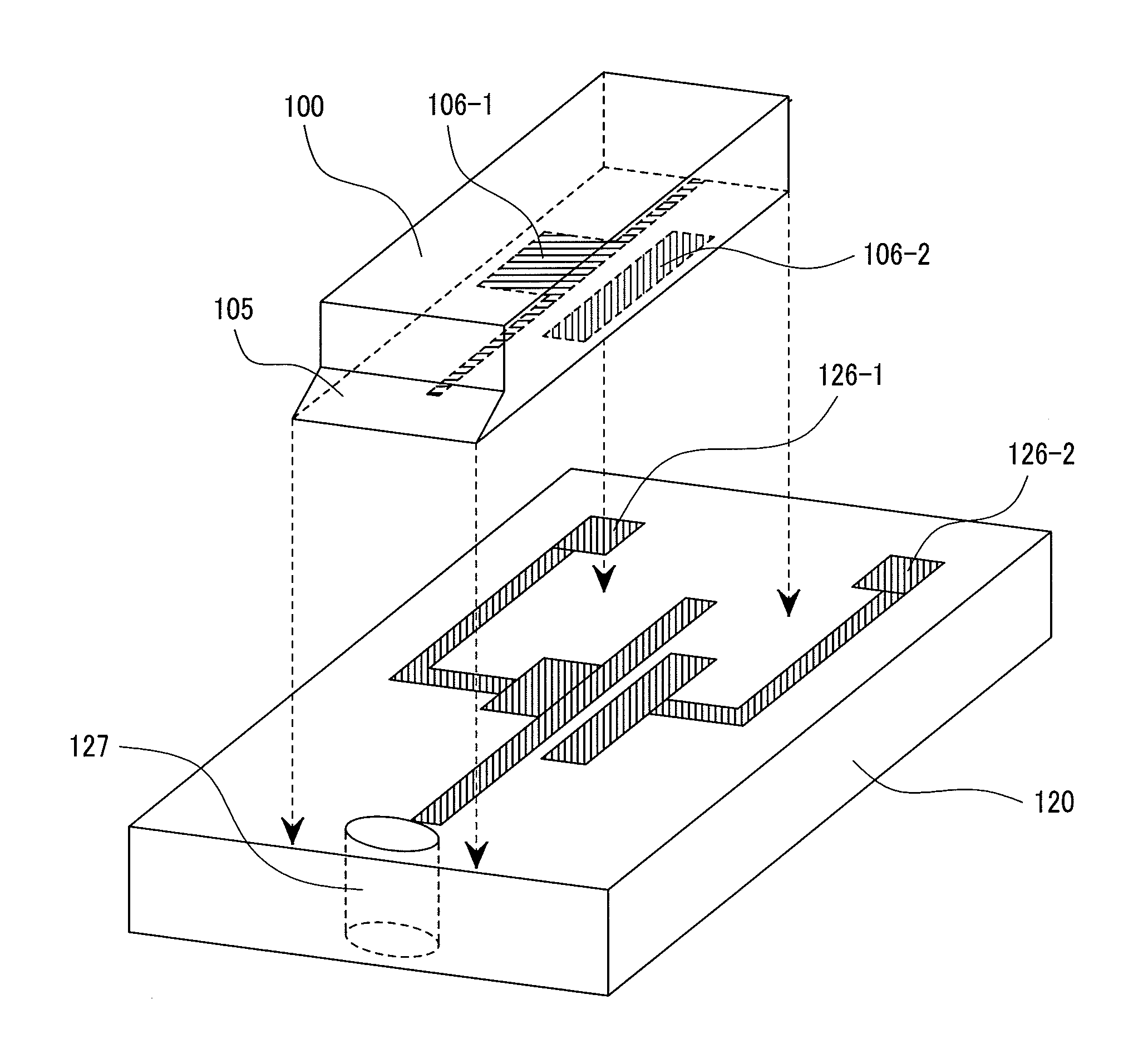
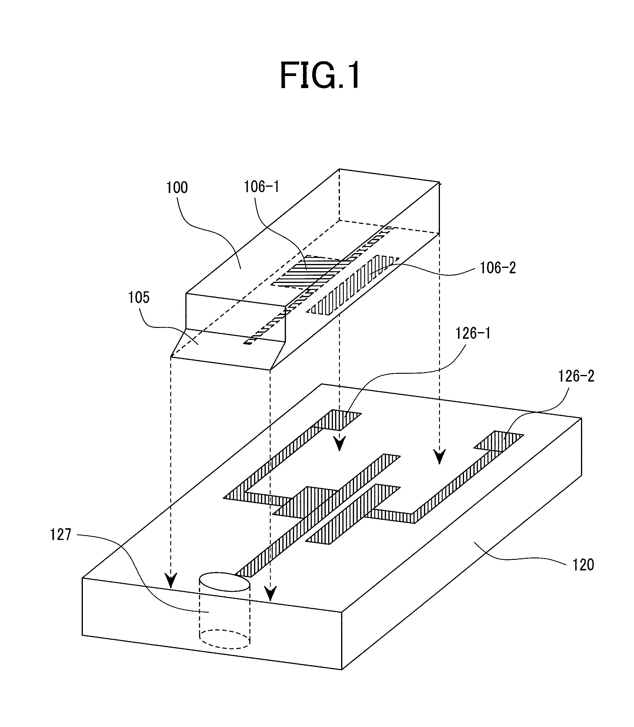
[0071]A laser diode has a monolithically integrated reflection mirror 105, and emits a light from a light emission surface 107. A laser diode 100 is mounted to the first surface 121 of a submount 120 in such a positional relation that a light transmits a structure 127 for allowing the light of the submount to pass therethrough. Electric leads 126 (126-1, 126-2) for driving the laser diode are disposed on the first surface 121 of the submount 120 and mounted being welded to electrodes 106 of the la...

embodiment 2

[0078]FIG. 5 is a perspective view schematically showing an optical device integrated head manufactured by mounting a semiconductor laser diode having a monolithically integrated reflection mirror on a submount as an embodiment of the invention and mounting the submount on a slider. FIG. 6A is a view showing a cross section of a laser diode along the direction of a cavity. FIG. 6B shows a perspective view for a magnetic transducer and coils to be mounted in FIG. 6A.

[0079]This embodiment is different from the embodiment 1 in view of the structure of the submount. In this structure, a submount 120 is cut to form a micro-lens structure 129. For a light transmitting structure 127, a material transparent to the emission wavelength of a laser diode, that is, a material having a large band gap may be used.

embodiment 3

[0080]FIG. 7 is a perspective view showing a structure of attaining active alignment by using a laser diode, a reflection mirror, a submount, and a slider as a preferred embodiment of the invention. FIG. 8A is a view showing a cross section of a laser diode along the direction of a cavity. FIG. 8B is a perspective view of a magnetic transducer and coils to be mounted in FIG. 8A.

[0081]Active alignment is conducted by using an edge-emitting laser diode 10 and a reflection mirror 131 for converting the propagating direction of a light of the laser diode instead of the surface emitting laser diode having the mirror integrated to the laser diode of the embodiment 1 to conduct mounting. With a viewpoint of a mounting space, a lens structure 132 is integrated with the mirror. It is simple and convenient to fix the mirror 131 to a groove 128 in the submount upon mounting the laser diode 10 and the reflection mirror 131 on the submount 120. Since the example of the mirror shown in the drawin...


PUM

PropertyMeasurementUnit
angleaaaaaaaaaa
angleaaaaaaaaaa
angleaaaaaaaaaa

Abstract

An optical device integrated head having high light utilizing efficiency by decreasing the propagation loss caused from an optical source to a recording medium, conducting by mounting according to compact active alignment method for efficiently guiding a light generated from a laser device to the top end of a head, in which a light source device mounted on a submount has a mirror portion having an inclinated surface to at least a portion of one edge thereof for reflecting an output light from the optical source device at the inclinated surface, a structural member including a lens structure for further allowing a light to pass through the submount, and an optical waveguide disposed passing through a slider for mounting the submount, and the optical source and the slider are positioned by using active alignment of light in a chip-on carrier structure having the optical source device mounted on the submount.

Description

CLAIM FOR PRIORITY[0001]The present application claims priority from Japanese application JP 2007-163999, filed on Jun. 21, 2007, the content of which is hereby incorporated by reference into this application.BACKGROUND OF THE INVENTION[0002]1. Field of the Invention[0003]The present invention concerns an optical device integrated head and it particularly relates to an optical device integrated head having a structure for guiding a laser light to a recording medium in an information recording apparatus at high recording density, an optical recording apparatus having an optical recording medium and means for writing to the recording medium by a laser light, and an optical-magnetic hybrid recording apparatus having a magnetic recording medium, writing means to the recording medium by magnetic fields and means for heating the recording medium by a laser light.[0004]2. Description of the Related Arts[0005]Along with development of the information society in recent years, digitalization ...

Claims


Application Information

Patent Timeline
Patent Type & Authority Patents(United States)
IPC IPC(8): G11B7/00G11B11/00
CPCG11B5/314G11B7/1387G11B2005/0021
Inventor SHIMIZU, JUNICHIROSHISHIKURA, MASATO
Owner HITACHI LTD
Learn More