
Solar power capacitor alternative switch circuitry system for enhanced capacitor life

a technology capacitors, applied in the field of solar power capacitors, can solve the problems of undesirable consequences, long life remains necessary, application does not last long, etc., and achieve the effects of long life, reliable components, and economic benefits

Inactive Publication Date: 2011-04-05
AMPT
View PDF270 Cites 231 Cited by
  • Summary
  • Abstract
  • Description
  • Claims
  • Application Information

AI Technical Summary

Benefits of technology

The present invention provides a way to use energy and supply desired power in a cost-effective and reliable manner. It offers a variety of aspects and embodiments that can be combined in different ways to achieve the desired goals. The invention includes a replacement system approach, highly reliable switch-mode topologies, an altered interim internal signal, unique control techniques, and devices and circuit inserts that can be broadly applied. The invention can be used in various applications such as power factor correction, solar inverters, and power supplies. It aims to provide economical, long-lasting, and reliable components for the system.

Problems solved by technology

Although there are applications where long life may not be necessary (perhaps such as some computer systems where a lifetime of five years is often adequate because the computer may be obsolete in this same time period) many applications do last long and long life remains necessary.
A grid-tied PV system is but one example of a system where the initial installation and product cost can be high enough, and the economics of using such a system may be such that payback needs to be considered as power is generated or as the system or device is used over a long period of time.
If the expectation is that the converter must be replaced every five or perhaps seven years, then there is an undesirable consequence that the converter must be replaced about four or more times over the life of the system or the investment.

Method used


Image

  • Solar power capacitor alternative switch circuitry system for enhanced capacitor life
  • Solar power capacitor alternative switch circuitry system for enhanced capacitor life
  • Solar power capacitor alternative switch circuitry system for enhanced capacitor life

Examples


Embodiment Construction

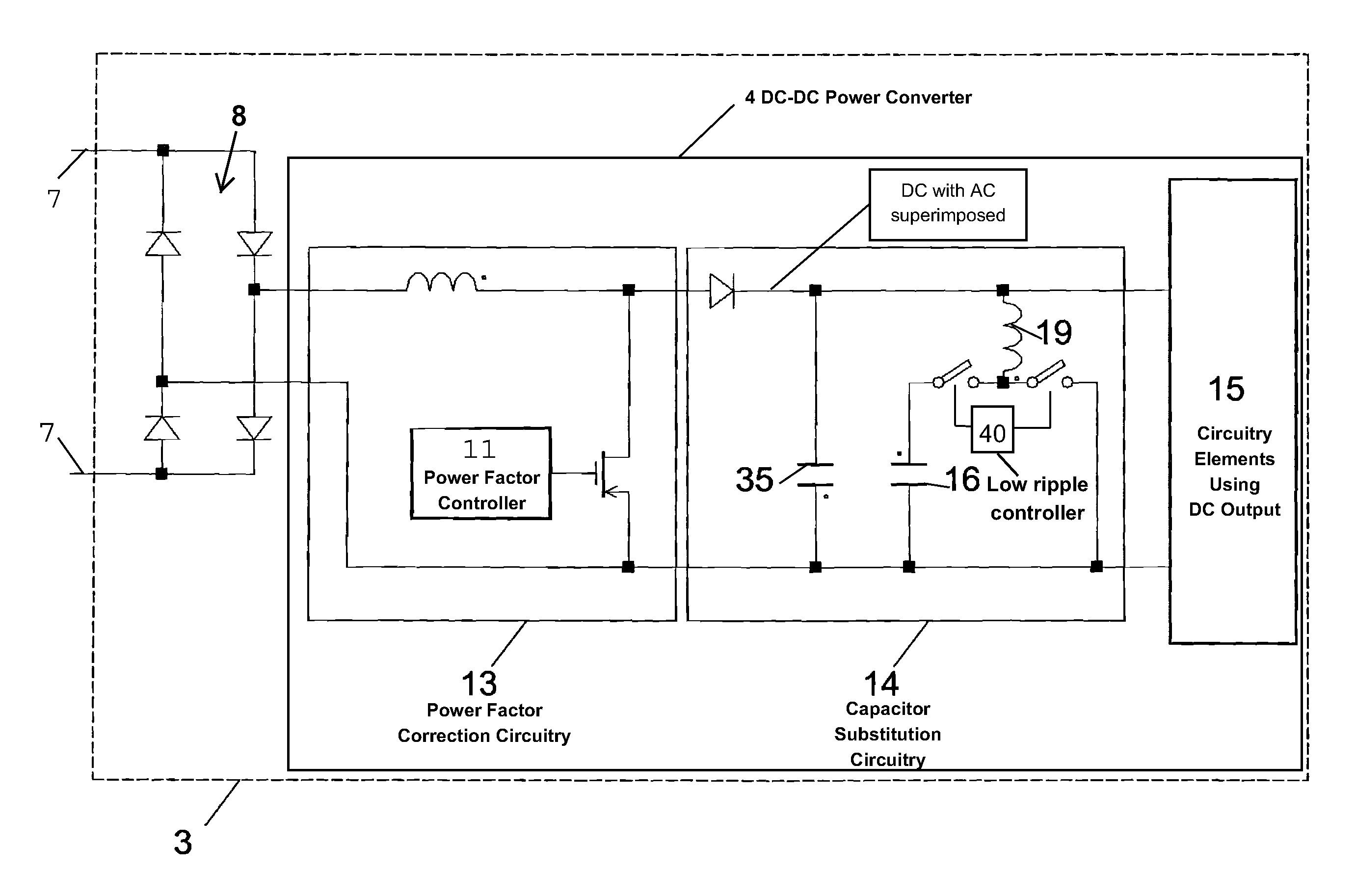
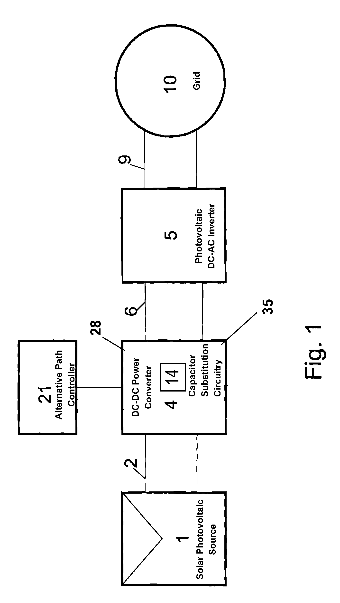
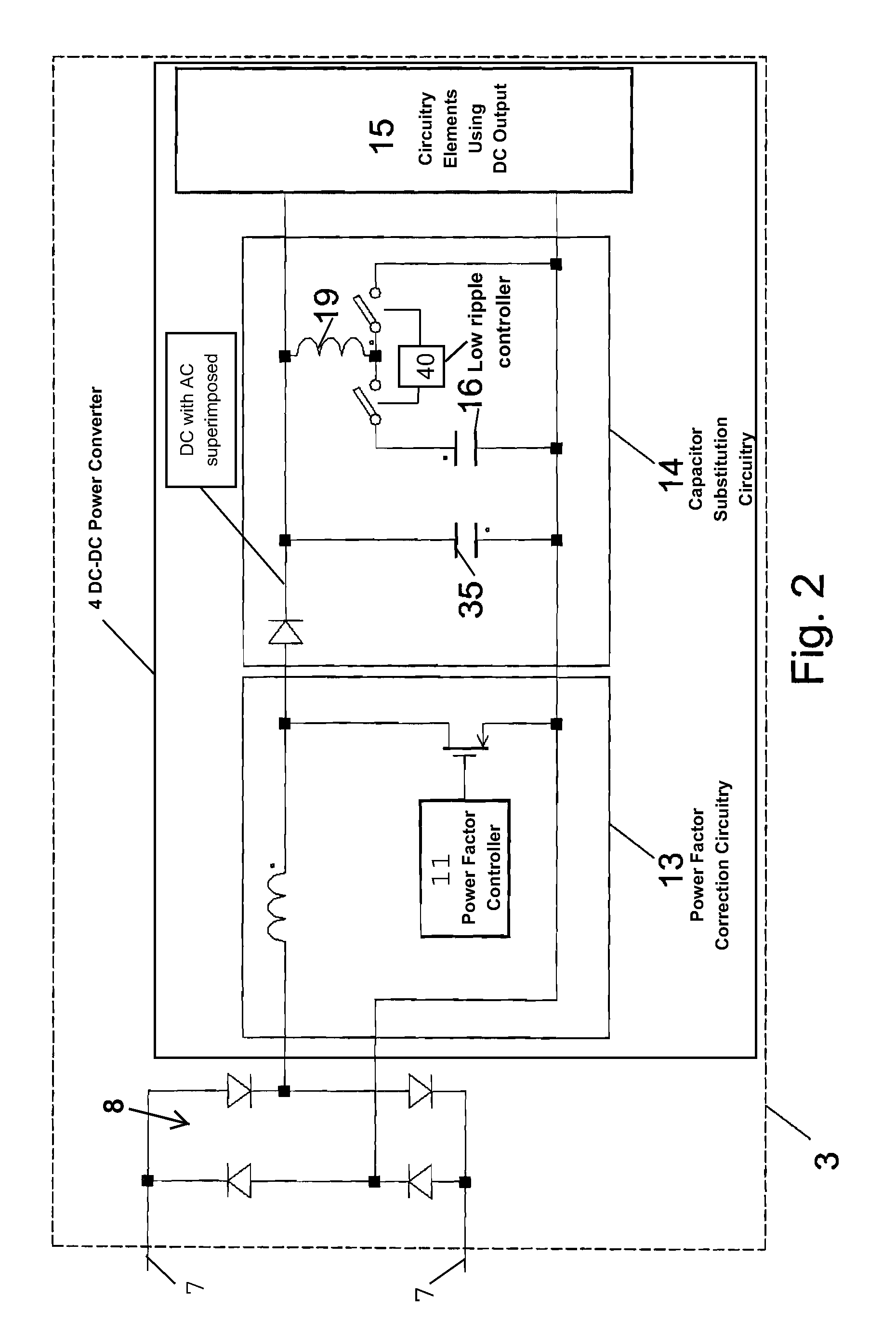
[0026]As mentioned above, the invention discloses a variety of aspects that may be considered independently or in combination with others. Although shown in initial applications such as a solar power system or as an accessory for a device with factor correction, other applications can, of course, exist. Initial understandings can begin with understanding an embodiment as applied to a solar energy power system. Such a system may combine any of the following concepts and circuits including: an inverter, a converter, energy storage, switches, a controller and changeable functional control components. Aspects may include a very high efficiency photovoltaic converter. Initial benefits are discussed individually and in combination in the following discussion as well as how each represents a general group of designs rather than just those initially disclosed.

[0027]FIG. 1 shows one embodiment of a solar energy power system illustrating the basic conversion and inversion principles of the pr...


PUM


Abstract

Reliability enhanced systems are shown where an short-lived electrolytic capacitor can be replaced by a much smaller, perhaps film type, longer-lived capacitor to be implemented in circuits for power factor correction, solar power conversion, or otherwise to achieve DC voltage smoothing with circuitry that has solar photovoltaic source (1) a DC photovoltaic input (2) internal to a device (3) and uses an enhanced DC-DC power converter (4) to provide a smoothed DC output (6) with capacitor substitution circuitry (14) that may include interim signal circuitry (28) that creates a large voltage variation for a replaced capacitor (16). Switchmode designs may include first and second switch elements (17) and (18) and an alternative path controller (21) that operates a boost controller (22) and a buck controller (23) perhaps with a switch duty cycle controller (32).

Description

[0001]This application is the United States National Stage of International Application No. PCT / US2008 / 080794, Filed 22 Oct. 2008, and which claims benefit of and priority to U.S. Provisional Application No. 60 / 986,979 filed Nov. 9, 2007, U.S. Provisional Application No. 60 / 982,053 filed Oct. 23, 2007, each hereby incorporated in their entirety herein by reference.TECHNICAL FIELD[0002]This invention relates generally to the field of designing and supplying DC power internally or externally in a device such as where low frequency AC ripple may be present. It has particular application to the technical field of power factor correction circuitry and to circuitry for solar power, specifically, methods and apparatus for converting electrical power from some type of solar energy source to make it available for use in a variety of applications. In the field of solar power it can be particularly useful in providing methods and apparatus for grid- or electrical power network-tied photovoltai...

Claims


Application Information

Patent Timeline
Patent Type & Authority Patents(United States)
IPC IPC(8): G05F1/46
CPCG05F5/00Y10S323/906
Inventor PORTER, ROBERT M.LEDENEV, ANATOLI
Owner AMPT
Learn More