
Explosive matrix assembly

a matrix and explosive technology, applied in the field of explosives, can solve the problems of inherently dangerous explosive disposal operations, increased collateral property damage, and more likely death or injury of bomb technicians during explosive disposal operations, so as to maximize the effect of explosive charge, increase the net explosives, and maximize the tensile strength of counter-charges

Inactive Publication Date: 2011-03-29
UNITED STATES ROBERT G HILTON ATTORNEY COMML LITIGATION BRANCH U S DEPT OF JUSTICE THE
View PDF13 Cites 16 Cited by
  • Summary
  • Abstract
  • Description
  • Claims
  • Application Information

AI Technical Summary

Benefits of technology

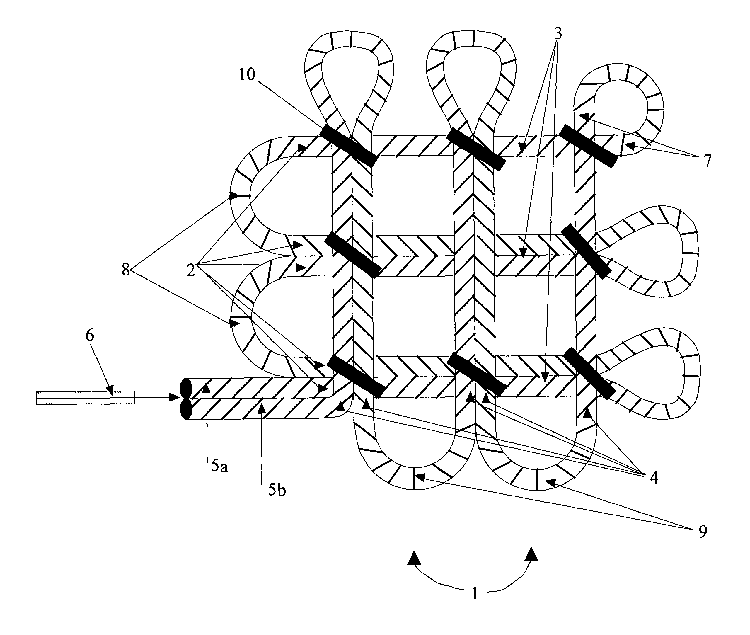
"The present invention is an explosive matrix design that can be easily, quickly, safely, reliably, and affordably prepared in the field and deployed by a single explosives operator. It allows for the construction of more efficient, safer, and less costly explosive counter charges. The detonating cord in the matrix is pre-assembled and stored in a flat and stacked manner, or can be deployed by robot. The design also allows for the use of commercially available detonating cord and reduces the need for pre-assembled nets. The detosion wave can propagate through the entire matrix without having to turn sharp corners, ensuring complete detonation. The concentration of detosioning cord at every intersection throughout the matrix ensures propagation of the detosion wave throughout the assembly. The invention maximizes the surface area of the counter charge in relation to the target, requiring less N.E.W. to counter any given threat than prior art matrices. The user can adjust the N.E.W. of the charge by changing the geometry and the explosive strength of the detosioning cord, and the surface area of the matrix can be easily enlarged by using cable ties to join many smaller charges into larger charges."

Problems solved by technology

Explosives disposal operations are inherently dangerous.
Bomb technicians are more likely to be killed or injured while conducting an explosives disposal operation than any other mission, including attempting to render an improvised explosive device (bomb) inoperative.
The higher the N.E.W. of the explosives, the greater the risk of injury and collateral property damage.
The greater the common surface area that the explosives counter charge has with the disposal target, the more likely the disposal target will be completely consumed.
These requirements are difficult to satisfy.
Such applications require significant manpower and financial resources.
Field assembly is not practical because they are a complex of multiple lengths of detonating cords joined together.
In addition, prior art explosive matrices are heavy and cumbersome to transport.
They use rope or cord to hold the detonating cord together, creating undesirable bulk and weight.
As a result, detonating cord can fail to propagate the detonation wave where the cord makes sharp turns, especially when large grain detonating cord is used.
This adds further complexity and bulk to these prior art designs.
Moreover, use of low grain non-propagating detonating cord is not always possible in prior designs.
Some prior art devices initiate at one point, in one direction, and use multiple lengths of detonating cord, which compromises reliability.
Other prior art incorporates multiple initiation points and multiple lengths of detonating cord, again making the design more complex and the assembly more complicated and expensive.
Many of these adapted designs are time consuming to construct and require large amounts of N.E.W. to be effective, resulting in greater risk of injury and unintended damage.
Lastly, many of such explosives are costly and difficult to acquire.

Method used


Image

  • Explosive matrix assembly
  • Explosive matrix assembly
  • Explosive matrix assembly

Examples


Embodiment Construction

Referring to the drawings, FIG. 1 depicts a preferred embodiment of the explosive matrix assembly 1 according to the present invention. The explosive charge is provided by a single length of detonating cord 2 that is configured into a first set of at least five parallel straight portions 3 lying in a first plane. Four of the straight portions are paired into two pairs. There is a space, usually about two inches, separating the two pairs from each other, and about two inches separating the unpaired straight portion from the nearest paired straight portion. The detonating cord is further configured so that there is a second set of at least five more parallel straight portions 4 that are orthogonal to the first set and lying in a second plane. The second set of straight portions 4 are paired and spaced in a manner similar to the first set of straight portions 3. Finally, the detonating cord is further configured so that there are two portions, 5a and 5b, referred to herein as “tails,” ...


PUM

PropertyMeasurementUnit
perimeteraaaaaaaaaa
lengthaaaaaaaaaa
surface areaaaaaaaaaaa

Abstract

An explosive matrix assembly is provided in which a single detonating cord is configured into a first set of at least five parallel sets of paired portions lying in the same plane, with adjacent parallel pairs being spaced about two inches apart. The detonating cord is further configured so that there is a second set of at least five more parallel portions that are substantially orthogonal to the first set and that lie on top of the first set. Finally, the detonating cord is further configured so that there is a pair of portions that operably secure the matrix to an appropriate explosive initiator.

Description

FIELD OF THE INVENTIONThe present invention relates to explosives which are used to neutralize target explosives.BACKGROUND OF THE INVENTIONExplosives disposal operations are inherently dangerous. Bomb technicians are more likely to be killed or injured while conducting an explosives disposal operation than any other mission, including attempting to render an improvised explosive device (bomb) inoperative.Effective and efficient explosive disposals require a technician to safely deploy an explosives counter charge that maximizes the target surface area for a given net explosive weight (N.E.W.) of the explosives counter charge. The higher the N.E.W. of the explosives, the greater the risk of injury and collateral property damage. The greater the common surface area that the explosives counter charge has with the disposal target, the more likely the disposal target will be completely consumed. Efficient counter charge explosives must possess a sufficiently high detonation velocity in ...

Claims


Application Information

Patent Timeline
Patent Type & Authority Patents(United States)
IPC IPC(8): C06C5/04
CPCC06C5/04F41H11/14F42B33/06F42D5/04F42B1/00Y10T29/53978
Inventor MITCHELL, JON K.
Owner UNITED STATES ROBERT G HILTON ATTORNEY COMML LITIGATION BRANCH U S DEPT OF JUSTICE THE
Learn More