
In-vehicle electronic control apparatus having monitoring control circuit

a technology of electronic control apparatus and monitoring control circuit, which is applied in the direction of electrical control, program control, instruments, etc., can solve the problems of inconvenient high-speed communication start-stop synchronization method and increase in transmission data and reception data, and achieve rapid change

Active Publication Date: 2011-03-22
MITSUBISHI ELECTRIC CORP
View PDF5 Cites 8 Cited by
  • Summary
  • Abstract
  • Description
  • Claims
  • Application Information

AI Technical Summary

Benefits of technology

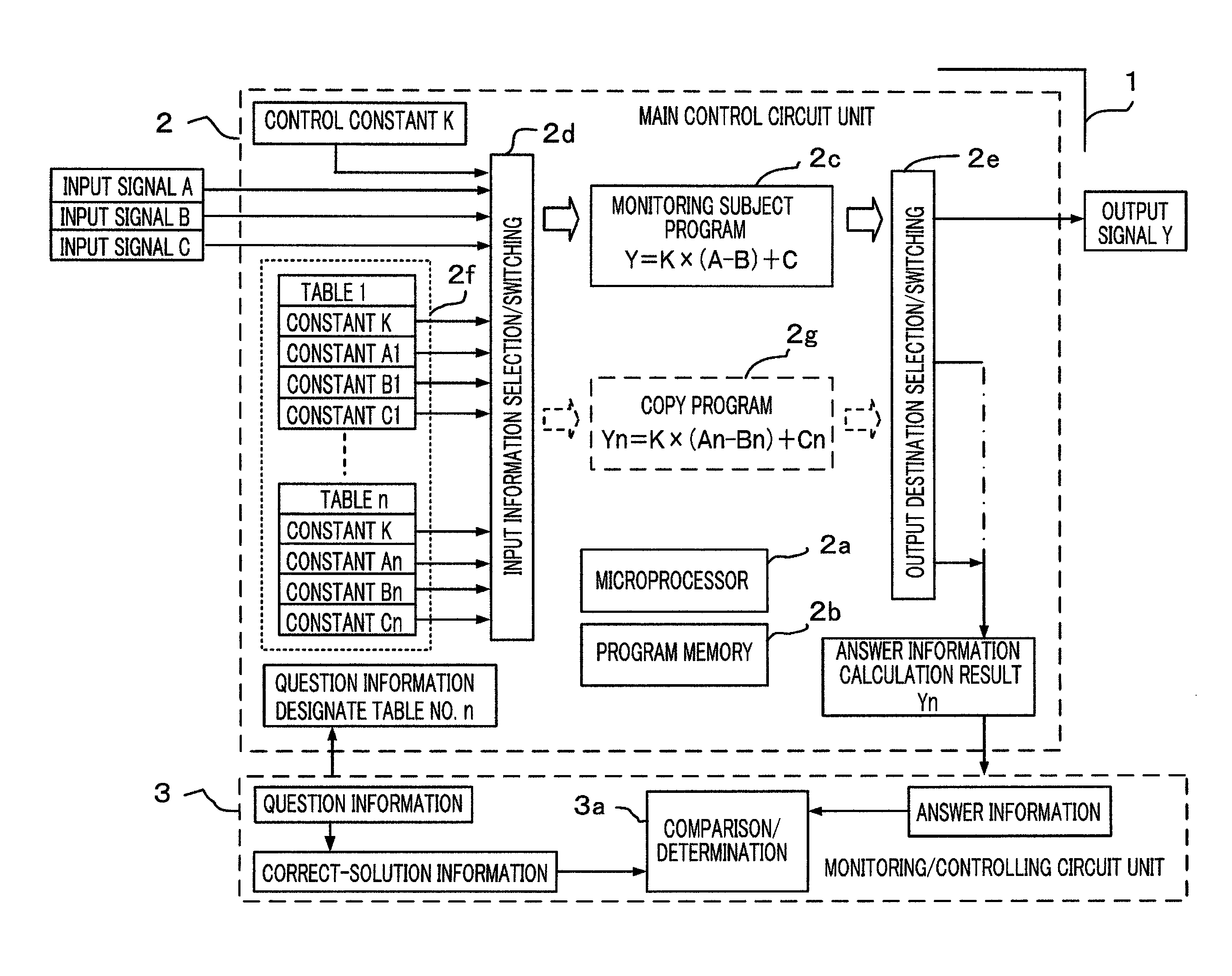
The present invention provides an in-vehicle electronic control apparatus with a monitoring control circuit unit that can perform periodic communication of input and output signals and abnormality monitoring. This allows for relatively frequent communication of input and output signals while reducing the control load on the main control circuit unit. The monitoring control circuit unit includes a question information generation unit, a correct-information storage memory, and an abnormality determination unit. The in-vehicle electronic control apparatus with a full-duplex block communication circuit and a question information updating unit can prolong the period of the abnormality monitoring signal and reduce the control load on the microprocessor.

Problems solved by technology

However, it has been a problem that, for the transmission data and the reception data, address information for designating the storage destination of the data and command information for discriminating the contents of the transmission data and the reception data are required, whereby the amounts of the transmission data and the reception data increase and the start-stop synchronization method is not suitable for high-speed communication.

Method used


Image

  • In-vehicle electronic control apparatus having monitoring control circuit
  • In-vehicle electronic control apparatus having monitoring control circuit
  • In-vehicle electronic control apparatus having monitoring control circuit

Examples


embodiment 1

(1) Configuration of in-Vehicle Electronic Control Apparatus According to Embodiment 1

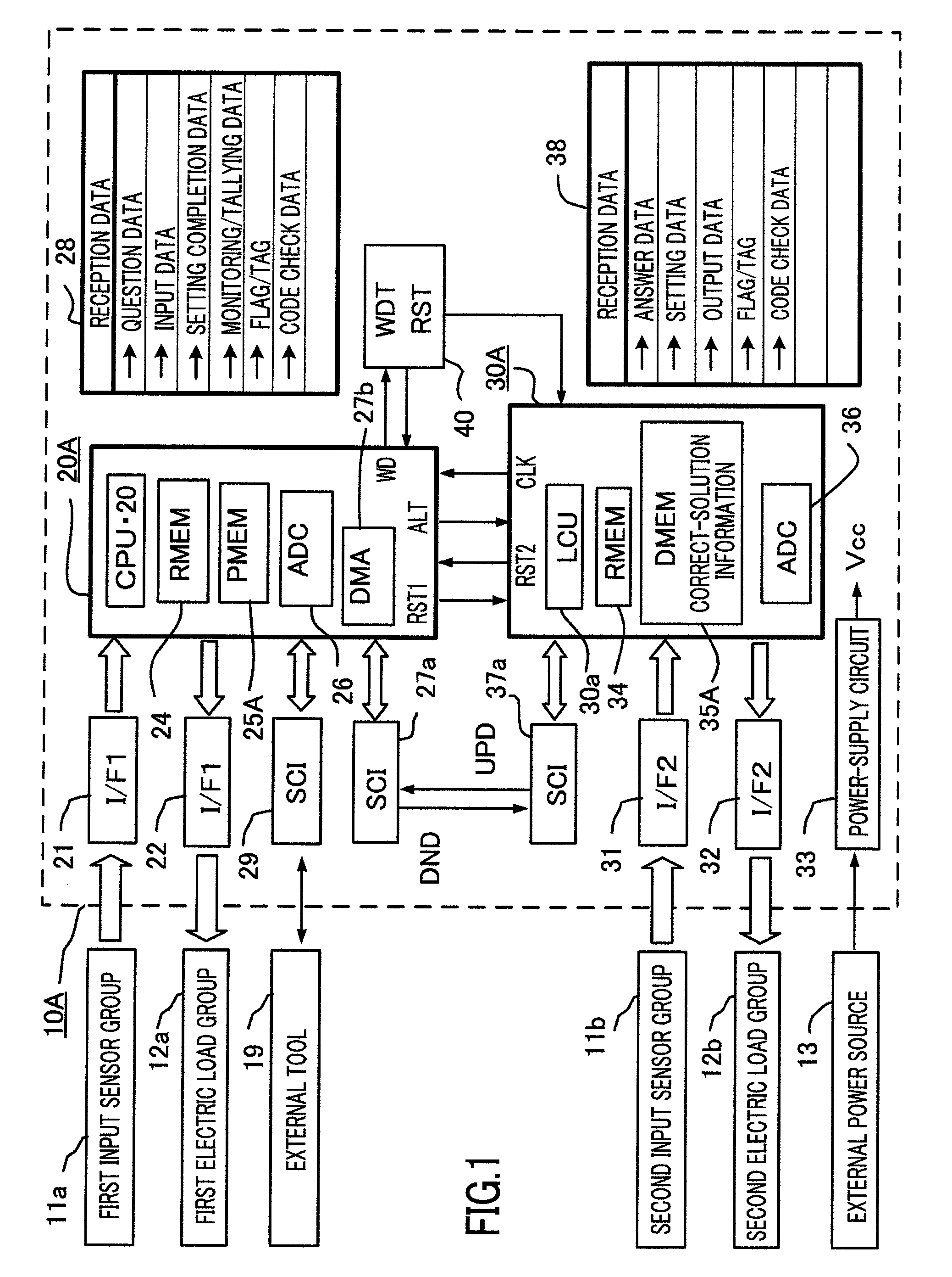
In the first place, the configuration of an in-vehicle electronic control apparatus according to Embodiment 1 of the present invention will be explained in detail. FIG. 1 is an overall block diagram of an in-vehicle electronic control apparatus, having a monitoring control circuit, according to Embodiment 1 of the present invention. In FIG. 1, an in-vehicle electronic control apparatus 10A is provided with a main control circuit unit 20A that is formed mainly of a microprocessor 20 and a monitoring control circuit unit 30A that is formed mainly of a logic circuit unit 30a; the in-vehicle electronic control apparatus 10A is configured in such a way as to receive electric power from an external power source 13, which is an in-vehicle battery, so as to operate.

A first input sensor group 11a externally connected to the electronic control apparatus 10A is configured, for example, with high-speed on / off ...

embodiment 2

(1) Configuration of in-Vehicle Electronic Control Apparatus According to Embodiment 2

The configuration of an in-vehicle electronic control apparatus according to Embodiment 2 will be explained in detail below, mainly with regard to what differs from the in-vehicle electronic control apparatus according to Embodiment 1. FIG. 8 is an overall block diagram illustrating an in-vehicle electronic control apparatus according to Embodiment 2 of the present invention. In FIG. 8, the same reference characters denote constituent elements that are the same as or equivalent to those in FIG. 1.

In FIG. 8, an in-vehicle electronic control apparatus 10B is provided with a main control circuit unit 20B formed mainly of a microprocessor 20 that collaborates with a program memory 25B and a monitoring control circuit unit 30B formed mainly of an auxiliary microprocessor 30b that collaborates with an auxiliary program memory 35B; the in-vehicle electronic control apparatus 10B is configured in such a wa...

embodiments 1 and 2

Supplement for Embodiments 1 and 2

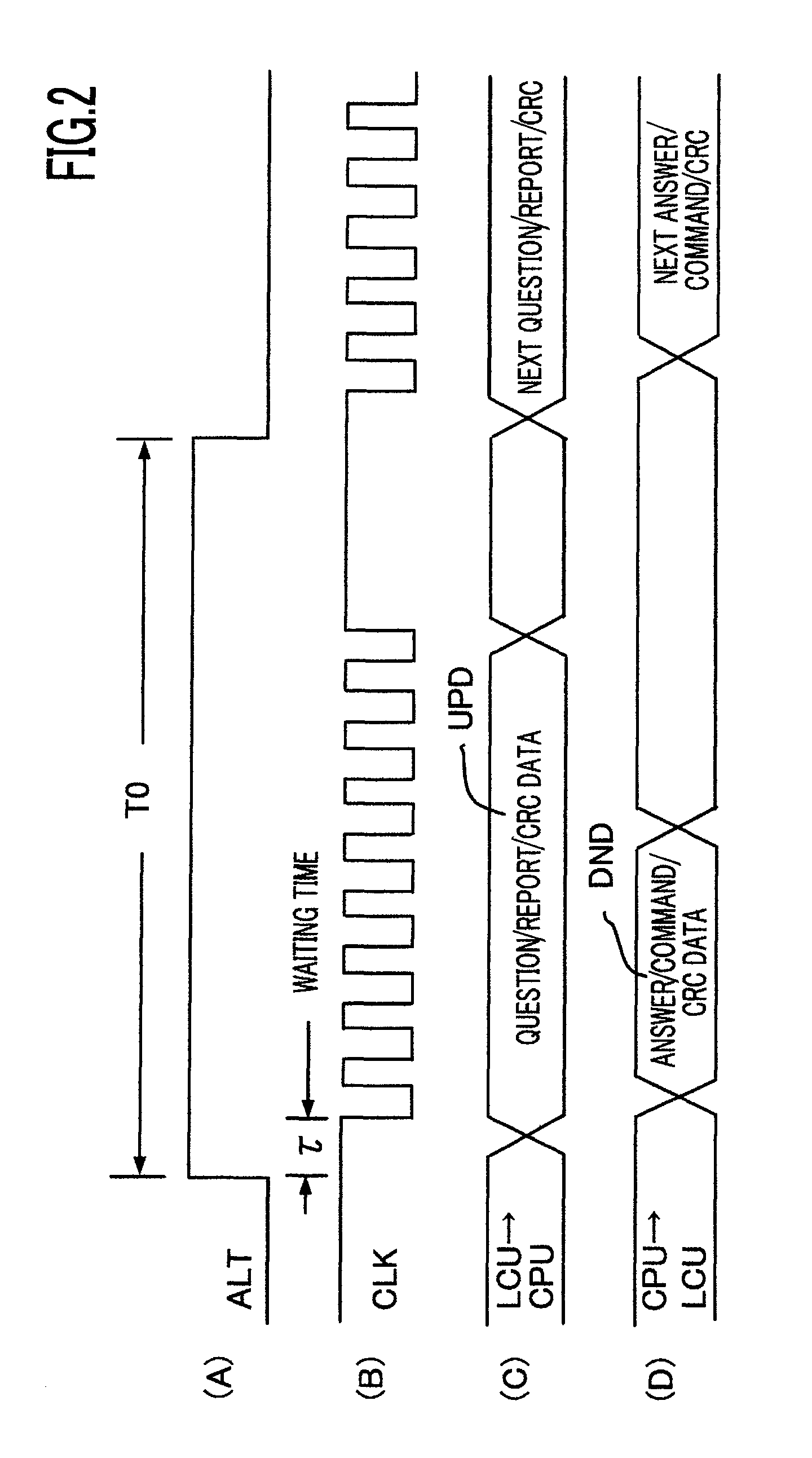
In the block communication circuit according to each of Embodiments 1 and 2, data included in a single communication instance incorporates information for all subject addresses; as a result, because the addresses for transmission destinations are preliminarily assigned in accordance with the transmission order, no address data for the transmission data is required; therefore, the amount of communication data is considerably reduced. As a result of collectively transmitting all the data, the abnormality monitoring signal is transmitted along with input and output signals that are relatively frequently communicated, and a problem occurs in which the control load on the microprocessor for generating the answer information increases; however, the substantial question occurrence period can be prolonged by use of the question information updating unit. Accordingly, an effect is demonstrated in which, by performing constant-period communication of the inpu...


PUM


Abstract

An in-vehicle electronic control apparatus, having a monitoring control circuit, according to the present invention is configured in such a way that serial interface circuits 27a and 37a are connected between a main control circuit unit 20A and a monitoring control circuit unit 30A, high-speed full-duplex block communication is performed by use of a communication permission signal ALT and a communication synchronization signal CLK, the same question information included in uplink communication information UPD is recurrently transmitted in a plurality times of communication and updated after being transmitted a predetermined times, and the main control circuit unit 20A returns answer information by use of downlink communication information DND, within a predetermined duration after the update of the question information; because the question update period is prolonged, the control load on the main control circuit unit 20A is reduced.

Description

BACKGROUND OF THE INVENTION1. Field of the InventionThe present invention relates to an in-vehicle electronic control apparatus incorporating a microprocessor and particularly to improvement of an in-vehicle electronic control apparatus, such as an engine control apparatus, which has a monitoring control circuit serially connected to the microprocessor in order to enhance the safety of the control.2. Description of the Related ArtIt is publicly known that, in an in-vehicle electronic control apparatus equipped with a microprocessor, a so-called Q&A-method abnormality determination unit is utilized in which, in order to always monitor whether or not the microprocessor functions normally, a monitoring control circuit unit is provided, the monitoring control circuit transmits question information to the microprocessor that serves as a main control circuit unit, the microprocessor sends the monitoring control circuit unit answer information in response to the question information, and t...

Claims


Application Information

Patent Timeline
Patent Type & Authority Patents(United States)
IPC IPC(8): G01M17/00F02D45/00G06F11/30
CPCF02D41/22F02D41/26F02D41/28G05B19/0421
Inventor IWAGAMI, YUKITANAKA, SUSUMUTSUNEKAZU, SHOSOISHII, AKIHIROHASHIMOTO, KOJI
Owner MITSUBISHI ELECTRIC CORP
Learn More