Bend bar quality control method for laser shock peening

a quality control method and laser shock technology, applied in the direction of manufacturing tools, material strength using steady bending forces, instruments, etc., can solve the problems of sacrificing samples for testing, affecting the quality of laser shock processing, so as to facilitate the production of readily measurable deformation, reliable and economical quality control tools, and the effect of reducing the number of tests

Inactive Publication Date: 2011-03-15
LSP TECH INC
View PDF16 Cites 1 Cited by
  • Summary
  • Abstract
  • Description
  • Claims
  • Application Information

AI Technical Summary

Benefits of technology

[0015]An advantage of the present invention is that the bend bar quality control test specimen and method provide a reliable and economical quality control tool for measuring the effects of compressive residual stresses in order to ensure consistency in laser peening operations.
[0016]Another advantage of the present invention is that the bend bar thickness can be chosen within a range that provides much more consistency in deformation results than is possible with conventional thin specimens.
[0017]Yet another advantage of the present invention is that the bar length can be chosen so as to facilitate production of a readily measurable deflection (i.e., at least about 0.010 inches) within the bend bar upon performing the given laser peening process thereon.
[0018]An even yet further advantage of the present invention is that the bend bar width can be chosen so as to facilitate the application of a particular laser peen pattern that is repetitive of the pattern being applied to the production components.
[0019]An even yet further advantage of the present invention is that the bend bar width can be chosen to facilitate an optimization in bend bar deflection considering the effects of bar material, bar geometry, and the laser peen pattern and intensity.
[0020]An even yet further advantage of the present invention is that the deflection in the bend bar can be quickly and easily measured using a simple dial gauge indicator, making the bend bar quality control method easily adaptable to laser peening operations.

Problems solved by technology

There are problems associated with monitoring and verifying the level of residual stresses developed in a part.
Residual stress measurements may be made using X-Ray diffraction (XRD) measurements or compliance methods (e.g., hole drilling, strain gauging with sectioning, etc.), but such methods are generally destructive in that samples must be sacrificed for testing.
In addition, these tests are time consuming, and the results are not available until after all the parts are processed.
The use of Almen strips to monitor laser peening has been attempted, but the results have been disappointing with considerable data scatter and poor reproducibility.
A specific drawback with the use of a standard steel Almen strip for use with laser peening is the limited thickness thereof.
This characteristic of the Almen strips make them unsuitable for monitoring laser shock processing.
While the Clauer® strips are relatively inexpensive and easy to use, the amount of bending is not necessarily a true measure of the residual stresses induced in the part, but rather a measure of the force applied to the tip of the strip.

Method used


Image

  • Bend bar quality control method for laser shock peening
  • Bend bar quality control method for laser shock peening
  • Bend bar quality control method for laser shock peening

Examples


Embodiment Construction

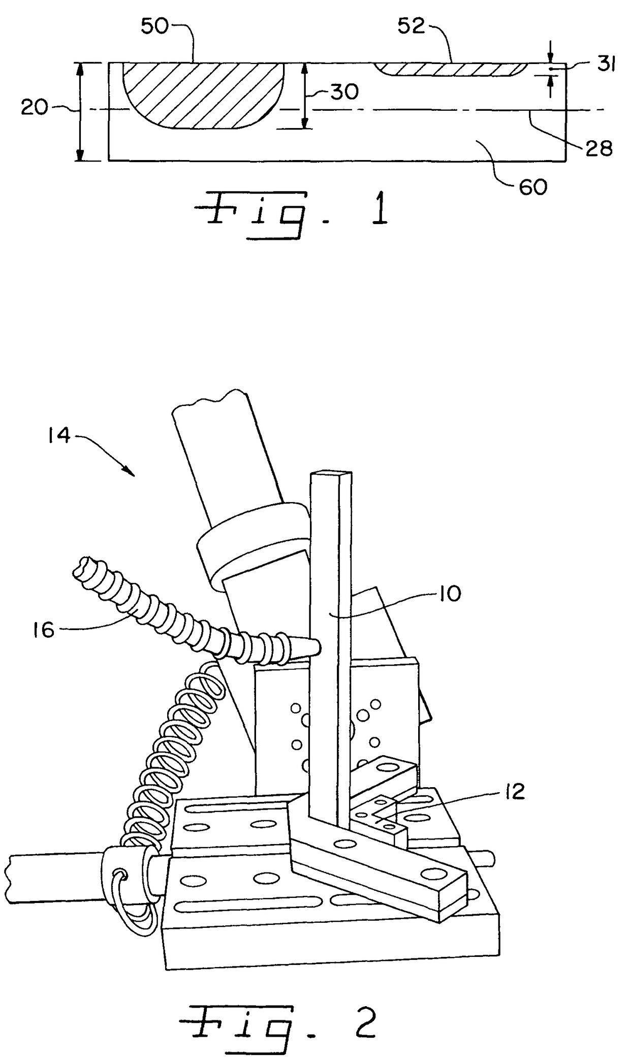
[0031]Referring now to the drawings, FIG. 1 shows an Almen strip 60 of thickness 20 having a laser peened surface 50 and a shot peened surface 52. The depth of compressive stress 30 under the laser peened surface extends beyond the mid-thickness plane 28 of the Almen strip 60, while the shot peened compressive stress depth 31 is far from the mid-thickness plane. A problem arises at laser peened surface so in that it is necessary that the depth 30 does not extend beyond the mid-thickness plane 28 of the Almen strip 60 to achieve consistent deflection measurements for process monitoring.

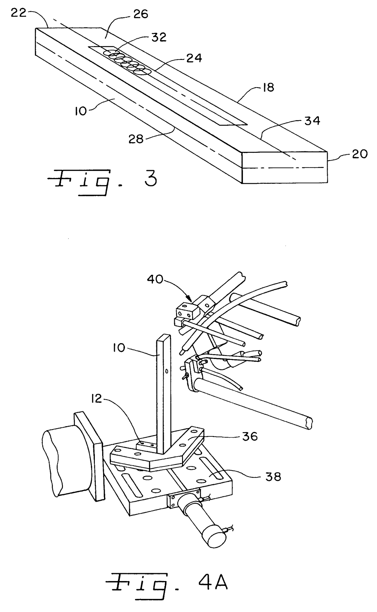
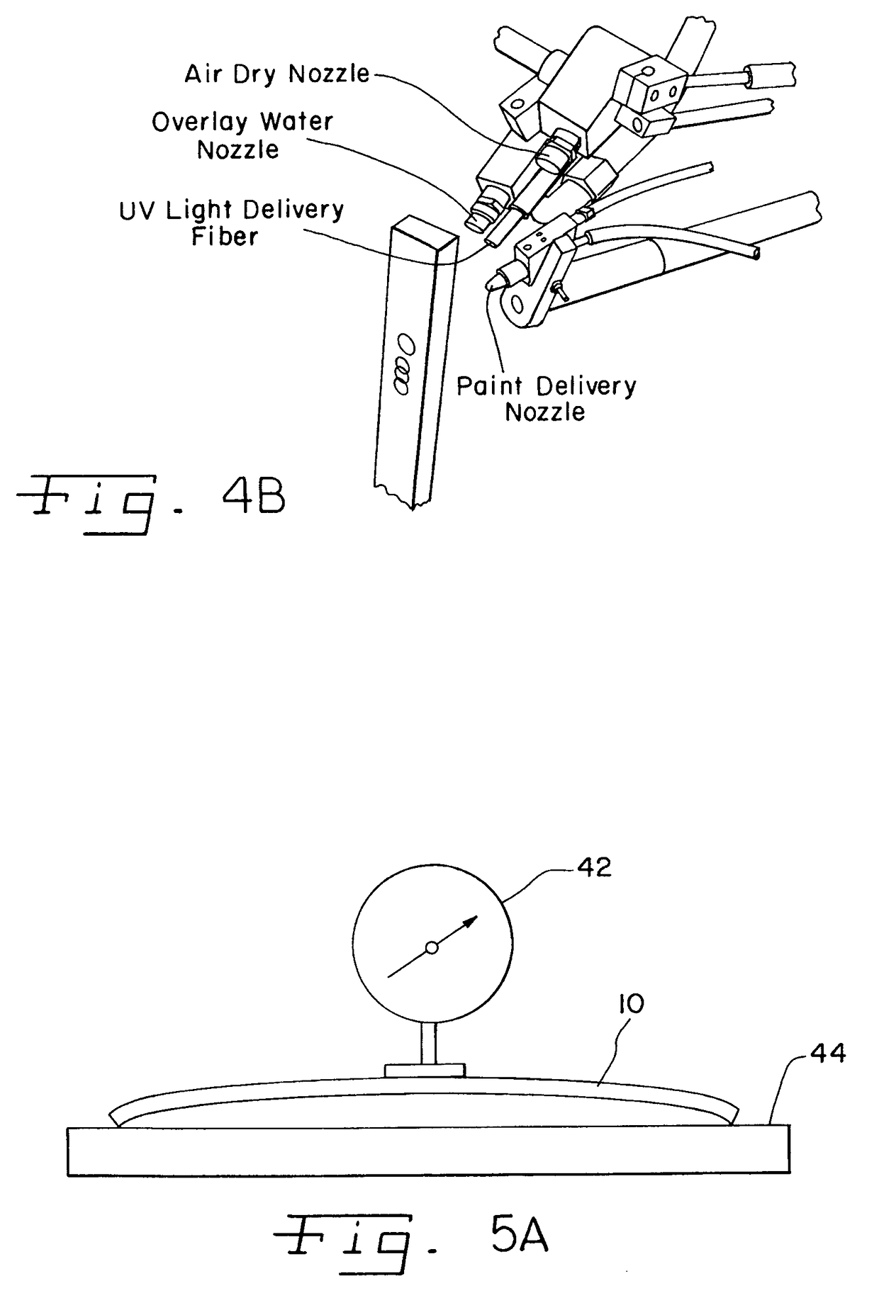
[0032]In FIG. 2, there is shown a bend bar 10 of the present invention for use in testing for the consistency of residual stress effects created during laser peening. Bend bar 10 is shown, mounted in a vise fixture 12, for treatment with a laser peening apparatus 14. The illustrated version of laser peening apparatus 14 (FIGS. 4A and 4B) includes a laser mechanism 15, transparent overlay delivery means...


PUM

PropertyMeasurementUnit
thicknessaaaaaaaaaa
thicknessaaaaaaaaaa
thicknessaaaaaaaaaa

Abstract

A bend bar is available for use in a quality control test for testing for a consistency of residual stress effects in a particular material using a given a laser peening process. The bar is composed of the particular material to be tested and has a bar length and a bar thickness. The particular material has a characteristic maximum stress penetration depth for compressive residual stresses that can be formed in using the given laser peening process. The bar thickness is chosen so as to be at least twice the characteristic maximum stress penetration depth. The bar has a test surface that extends parallel to the bar length and perpendicular to the bar thickness. After forming a spot pattern on the test surface using the given laser peening process, the deflection generated in the bar due to the compressive residual stresses induced by laser peening can then be measured and used as a quality control measurement.

Description

CONTINUATION DATA[0001]This application claims priority from U.S. Provisional Patent Application No. 60 / 528,569, filed on Dec. 10, 2003, the disclosure of which is herein explicitly incorporated by reference.BACKGROUND OF THE INVENTION[0002]1. Field of the Invention[0003]The present invention relates to an improved quality control method for laser shock processing in which the consistency of residual stress effects produced thereby are monitored and more specifically, relates to a quality control method which employs bend bars for such testing.[0004]2. Description of the Related Art[0005]Laser peening creates deep compressive residual stresses in the surface of a metal part being treated. Such compressive stresses beneficially improve the fatigue strength, fatigue life, fretting fatigue resistance, and stress corrosion cracking resistance of components.[0006]There are problems associated with monitoring and verifying the level of residual stresses developed in a part. Residual stres...

Claims


Application Information

Patent Timeline
Patent Type & Authority Patents(United States)
IPC IPC(8): B23K26/00
CPCC21D10/005G01N3/20G01N3/62G01N2203/0248G01N2203/0664
Inventor TENAGLIA, RICHARD D.CLAUER, ALLAN H.DULANEY, JEFF L.LAHRMAN, DAVID F.TOLLER, STEVE
Owner LSP TECH INC
Why Eureka
Try Eureka