
Control device and control method for powertrain, program for implementing the control method, and recording medium containing the program

a technology of control device and control method, which is applied in the direction of machines/engines, instruments, etc., can solve the problems of reducing affecting the operation of electric power generation performed using the rotary electric machine, and affecting the efficiency of regenerative braking operation, so as to reduce the shock

Inactive Publication Date: 2011-03-08
TOYOTA JIDOSHA KK +1
View PDF12 Cites 0 Cited by
  • Summary
  • Abstract
  • Description
  • Claims
  • Application Information

AI Technical Summary

Benefits of technology

The invention provides a control device and method for a powertrain that reduces shocks and improves stability. The control device includes an electric power generation restriction unit that restricts the use of the rotary electric machine for generating power, a control unit that controls the drive power source to transfer torque that does not decelerate the vehicle, and a shift control unit that changes gears when the torque is transferred. The method includes restricting the use of the rotary electric machine for generating power and controlling the drive power source and transmission to transfer torque that does not decelerate the vehicle. The vehicle may also have a brake system that increases braking force when the drive power source is controlled to transfer torque that does not decelerate the vehicle. The invention can be implemented using a computer program.

Problems solved by technology

However, the transfer of torque from the rotary electric machine to the wheels via the transmission may be temporarily interrupted when the transmission is shifted to a selected gear.
However, if the SOC (state of charge) of, for example, a battery is high, the generated electric power cannot be stored in the battery.
Therefore, the electric power generation performed using the rotary electric machine, i.e., the regenerative braking operation, is restricted.
As a result, the gears may contact each other, which causes a shock.

Method used


Image

  • Control device and control method for powertrain, program for implementing the control method, and recording medium containing the program
  • Control device and control method for powertrain, program for implementing the control method, and recording medium containing the program
  • Control device and control method for powertrain, program for implementing the control method, and recording medium containing the program

Examples


Embodiment Construction

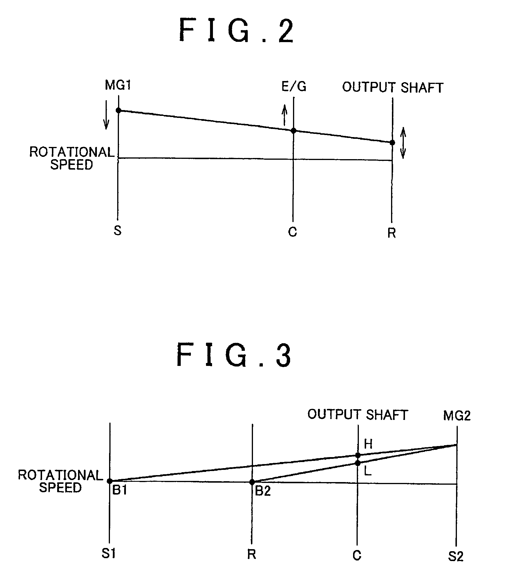
[0032]Hereafter, an embodiment of the invention will be described with reference to the accompanying drawings. The same reference numerals will be assigned to the same components. The names and functions of the components having the same reference numerals are also the same. Accordingly, the description concerning the components having the same reference numerals will be provided only once below.

[0033]A powertrain of a hybrid vehicle equipped with a control device according to an embodiment of the invention will be described with reference to FIG. 1. The control device according to the embodiment of the invention may be implemented when an ECU (Electronic Control Unit) 1000 executes a program stored in ROM (Read Only Memory) 1002 of the ECU 1000.

[0034]As shown in FIG. 1, the powertrain mainly includes an engine 100, a first motor generator (MG1) 200, a power split mechanism 300, a second motor generator (MG2) 400, and a transmission 500. The power split mechanism 300 may combine the...


PUM


Abstract

A shock caused due to a change in the direction of torque transferred to an output shaft is reduced. There is provided a control device for a powertrain including a drive power source that transfers torque to an output shaft connected to a wheel of a vehicle, and a rotary electric machine that transfers torque to the output shaft via a transmission. When electric power generation performed using the rotary electric machine is restricted, if torque that decelerates the vehicle is transferred from the drive power source to the output shaft, a control is executed so that torque that does not decelerate the vehicle is transferred from the drive power source to the output shaft, and a shift control over the transmission is executed.

Description

INCORPORATION BY REFERENCE[0001]The disclosure of Japanese Paten Application No. 2006-334381 filed on Dec. 12, 2006 including the specification, drawings and abstract is incorporated herein by reference in its entirety.BACKGROUND OF THE INVENTION[0002]1. Field of Invention[0003]The invention relates generally to a control device and control method for a powertrain, a program for implementing the control method, and a recording medium that contains the program, and, more specifically, to a technology for controlling a powertrain that includes a drive power source which transfers torque to an output shaft connected to wheels, and a rotary electric machine which transfers torque to the output shaft via a transmission.[0004]2. Description of Related Art[0005]Hybrid vehicles, in which an engine and a rotary electric machine, for example, a motor are used in combination as drive power sources, have been conventionally used. The torque output from the rotary electric machine is used to mov...

Claims


Application Information

Patent Timeline
Patent Type & Authority Patents(United States)
IPC IPC(8): B60W10/04B60W10/10B60W10/18B60K6/445B60K6/543B60K6/547B60L7/20B60L50/16B60T7/12B60W10/06B60W10/08B60W20/00F02D29/00F16H61/04F16H63/50
CPCB60K6/40B60K6/445B60K6/547B60W10/06B60W10/08B60W10/115B60W10/184B60W20/00B60K6/365B60K1/02Y10T477/24F16H3/728F16H63/502F16H2037/0873F16H2059/144F16H2200/2007F16H2200/2023F16H2200/2035Y02T10/6286Y02T10/6239Y10T477/23Y10T477/81Y02T10/62B60W10/18B60W10/10B60W10/02B60W20/15
Inventor UEJIMA, TAIYOENDO, HIROATSUTAJIMA, YOICHI
Owner TOYOTA JIDOSHA KK
Learn More