
An automobile air outlet blade transmission mechanism

A transmission mechanism and air outlet technology, which is applied in the field of auto parts, can solve the problems of complex structure of the transmission mechanism and inconvenient maintenance, and achieve the effect of good transmission effect, prevention of changing direction, and simple structure

Active Publication Date: 2019-02-05
CHUZHOU SHUNYU MOLD
View PDF9 Cites 0 Cited by
  • Summary
  • Abstract
  • Description
  • Claims
  • Application Information

AI Technical Summary

Problems solved by technology

[0002] At present, the dashboards of all cars and the center consoles of some cars are equipped with air outlets. The air outlets are the terminals of the vehicle air-conditioning system. A transmission mechanism is provided so that any one of the blades can be moved to realize the overall linkage of the blade group. In the patent CN201935346U, a transmission mechanism for the blades of the air outlet of the car is proposed. The instrument panel is covered, and only the blade group can be seen in the air outlet, which will not affect the appearance of the air outlet, so there is no need to install more blades to cover the connecting rod, and the adjustment of the blade angle is smoother, but it also exists The disadvantage is that the connecting rod has no fixing device after adjustment, and it is easy to change the direction of the blade by the vibration or gravity of the car, and the existing transmission mechanism is complex in structure, and it is very inconvenient to repair after damage. For this reason, we propose a car air outlet blade Transmission mechanism to solve the above problems

Method used


Image

  • An automobile air outlet blade transmission mechanism
  • An automobile air outlet blade transmission mechanism
  • An automobile air outlet blade transmission mechanism

Examples


Embodiment

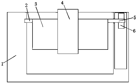
[0020] Embodiment: the first blade 3 on the device is movably installed in the automobile air outlet assembly housing 1 through the first rotating shaft 2 and the second rotating shaft 5, and the first rotating shaft 2 and the second rotating shaft 5 are connected with the automobile air outlet assembly respectively. The casing 1 is movably connected with the partition plate, the gear 6, the fixed column 11 and the elastic piece 12 are all located on the side of the partition plate away from the first blade 3, the adjacent first blades 3 are in line with each other, and the adjacent gears 6 Mesh with each other, the second blade 9 is movably installed in the automobile air outlet assembly housing 1 through the third rotating shaft 10, and the guide block 4 is held to swing and rotate up and down, and the guide block 4 drives one of the first blades 3 to swing and rotate up and down. The blade 3 drives a gear 6 to rotate through the second rotating shaft 5, and the gear 6 drives...


PUM


Abstract

The invention discloses an automobile air outlet blade transmission mechanism, which comprises an automobile air outlet assembly casing, a partition plate is arranged inside the automobile air outlet assembly casing, and a plurality of The first blade and the second blade, the first blade and the second blade are perpendicular to each other, and the adjacent first blades are parallel to each other, one end of the first blade is provided with a first rotating shaft, and the other end of the first blade is provided with a second A shaft, a gear is clamped on the second shaft, a guide block is sleeved on the outside of the first blade, a through hole is opened inside the guide block, the side wall of the through hole is slidingly connected with the first blade, the first shaft and The second rotating shaft is movably connected with the housing of the automobile air outlet assembly and the partition plate respectively, and the gears on the adjacent first blades mesh with each other, and the gears are located on a straight line. The invention has the advantages of simple structure, good transmission effect and locking function, which prevents the blades from being changed in direction by the vibration of the vehicle or the action of gravity.

Description

technical field [0001] The invention relates to the technical field of auto parts, in particular to an auto air outlet blade transmission mechanism. Background technique [0002] At present, the dashboards of all cars and the center consoles of some cars are equipped with air outlets. The air outlets are the terminals of the vehicle air-conditioning system. A transmission mechanism is provided so that any one of the blades can be moved to realize the overall linkage of the blade group. In the patent CN201935346U, a transmission mechanism for the blades of the air outlet of the car is proposed. The instrument panel is covered, and only the blade group can be seen in the air outlet, which will not affect the appearance of the air outlet, so there is no need to install more blades to cover the connecting rod, and the adjustment of the blade angle is smoother, but it also exists The disadvantage is that the connecting rod has no fixing device after adjustment, and it is easy to...

Claims


Application Information

Patent Timeline
Patent Type & Authority Patents(China)
IPC IPC(8): B60H1/34
CPCB60H1/3414
Inventor 熊学兵张咏汪求军
Owner CHUZHOU SHUNYU MOLD
Learn More