Gate driving circuit and driving circuit unit thereof

a driving circuit and gate technology, applied in logic circuit coupling/interface arrangement, pulse technique, instruments, etc., can solve the problems of high production cost when using the external gate driver, inability to operate corresponding scan lines properly, and increased scan line load accordingly, so as to prevent the circuit from the heat effect problem, the effect of improving the output of driving signals

Active Publication Date: 2011-03-01
AU OPTRONICS CORP
View PDF9 Cites 8 Cited by
  • Summary
  • Abstract
  • Description
  • Claims
  • Application Information

AI Technical Summary

Benefits of technology

[0008]It is therefore an aspect of the present invention to provide a gate driving circuit and a driving circuit unit thereof, so as to improve outputted driving signals and prevent the circuit from the heat effect problem.
[0011]According to the embodiments of the present invention, the gate driving circuit and the driving circuit unit thereof can be used to improve outputted driving signals, output enough driving current and prevent the circuit from the heat effect problem.

Problems solved by technology

However, the production cost is expensive when using the external gate driver.
However, when producing a large liquid crystal display, the loads of the scan lines increase accordingly.
Therefore, due to the increasing loads, the driving signals would be distorted, so that the corresponding scan lines cannot be operated properly.
Besides, transistors in the gate driving circuit also have to become relatively bigger, so as to output enough current to drive the scan lines, and the heat effect in the circuit is therefore more serious.

Method used


Image

  • Gate driving circuit and driving circuit unit thereof
  • Gate driving circuit and driving circuit unit thereof
  • Gate driving circuit and driving circuit unit thereof

Examples


Embodiment Construction

[0019]Detailed illustrative embodiments of the present invention are disclosed herein. However, specific details disclosed herein are merely representative for purposes of describing exemplary embodiments of the present invention. This invention may, however, be embodied in many alternate forms and should not be construed as limited to the embodiments set forth herein.

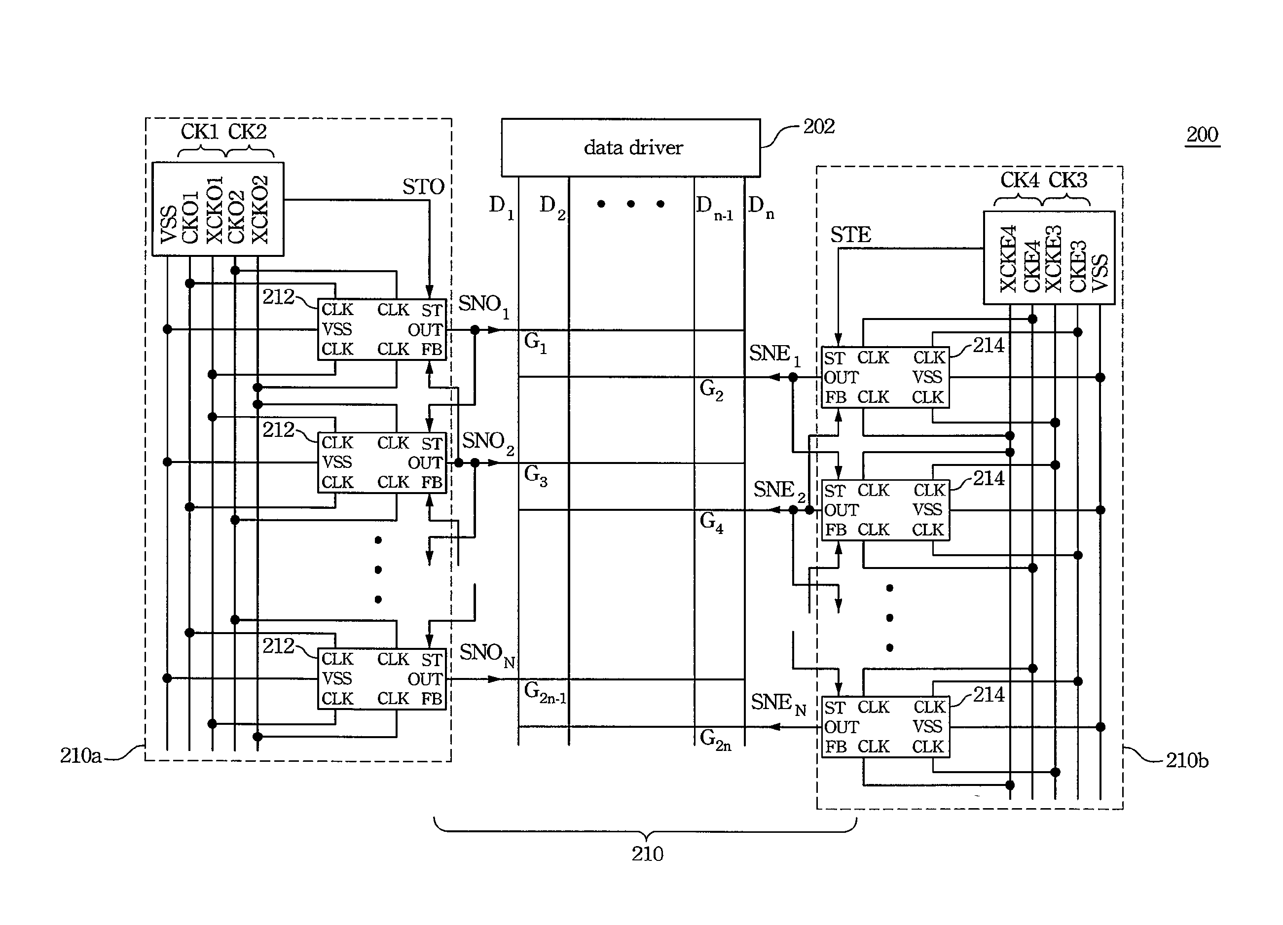
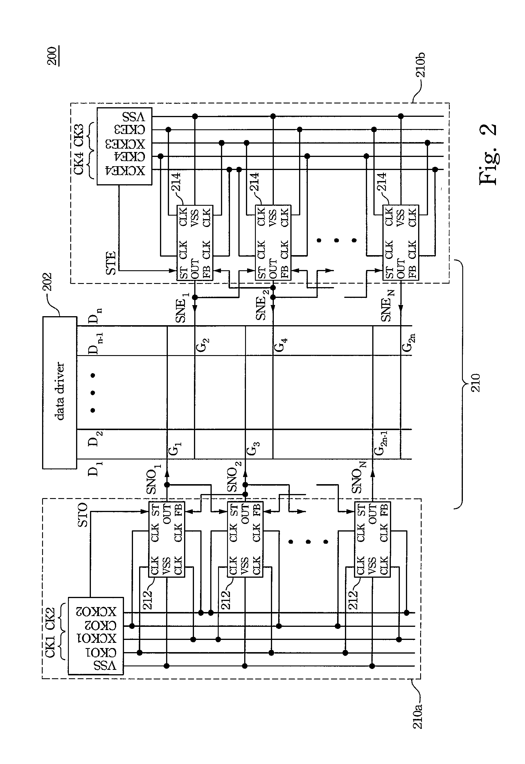
[0020]FIG. 2 shows a liquid crystal display panel according to one embodiment of the present invention. The liquid crystal display panel 200 includes data lines D1 . . . Dn, scan lines G1 . . . G2n, a data driver 202 and a gate driving circuit 210, and the gate driving circuit 210 drives the scan lines G1 . . . G2n. The gate driving circuit 210 is separated into a first gate driving circuit 210a and a second gate driving circuit 210b, and the first gate driving circuit 210a includes first circuit units 212 and the second gate driving circuit 210b includes second circuit units 214. The first circuit units 212 is coupled...


PUM


Abstract

A driving circuit unit outputting a driving signal includes an input unit, an assistant output unit and an output unit. The input unit is coupled to an input node and receives a start signal to make the input node have a potential. The assistant output unit receives a first clock signal to increase the potential of the input node. The output unit receives a second clock signal to increase the potential of the input node and outputs the driving signal. A gate driving circuit is also disclosed.

Description

RELATED APPLICATIONS[0001]This application claims priority to Taiwan Application Serial Number 95146930, filed Dec. 14, 2006, which is herein incorporated by reference.BACKGROUND[0002]1. Field of Invention[0003]The present invention relates to a gate driving circuit and a driving circuit unit thereof. More particularly, the present invention relates to a gate driving circuit and a driving circuit unit thereof in a liquid crystal display.[0004]2. Description of Related Art[0005]In a conventional liquid crystal display, there is always an external gate driver used to drive scan lines of the liquid crystal display. However, the production cost is expensive when using the external gate driver. Therefore, lowering the production cost for the gate driver is very important.[0006]In the prior art, a gate driving circuit fabricated on a glass substrate is used to output the gate driving signals to the scan lines, so as to replace the external gate driver used before and lower the production ...

Claims


Application Information

Patent Timeline
Patent Type & Authority Patents(United States)
IPC IPC(8): G09G5/02
CPCG09G3/3674G11C19/184G11C19/28H03K19/01721
Inventor CHIEN, CHIH-YUANKUO, YU-JUCHEN, WAN-JUNG
Owner AU OPTRONICS CORP
Why Eureka
Try Eureka