
Implementation of ultra wide band (UWB) electrically small antennas by means of distributed non foster loading

a technology of electrically small antennas and distributed loading, which is applied in the direction of antennas, antenna details, antenna feed intermediates, etc., can solve the problems of low q factor of antennas, high bandwidth of operation, and unrecognised frequency behavior of loads, and achieves the effect of easy retrofi

Inactive Publication Date: 2011-03-01
THE OHIO STATES UNIV
View PDF4 Cites 55 Cited by
  • Summary
  • Abstract
  • Description
  • Claims
  • Application Information

AI Technical Summary

Benefits of technology

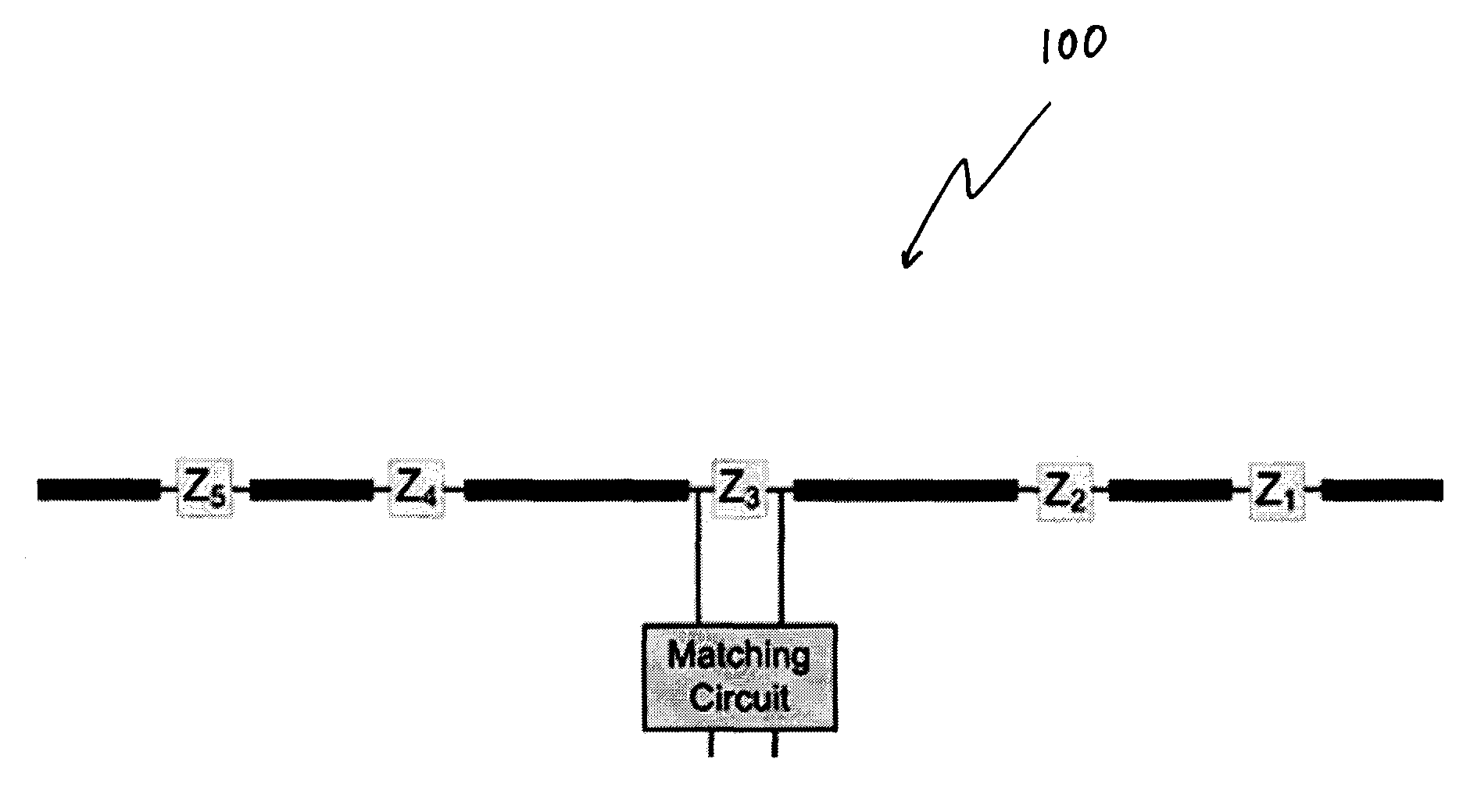
[0010]Various other benefits or advantages of exemplary embodiments of the present invention may include one or more of the following: 1) easy retrofit with existing infrastructure, as added active loads may work with existing antennas; 2) using loads, the antenna current shape (and pattern shape) may be controlled over a desired band; 3) loaded antennas may be operated with less complex matching networks; 4) may be utilized in building an integrated antenna (e.g., on chip Technology—in other words, compatible with VLSI technology); and 5) may be no need to use exotic materials with hard to obtain electrical properties to achieve UWB antennas.

Problems solved by technology

However, the frequency behavior of the loads has not been discussed yet in the known art.
Furthermore, such loading may lower the Q factor of the antenna allowing a much higher bandwidth of operation than what conventional antennas can achieve if complemented with a passive matching network.

Method used


Image

  • Implementation of ultra wide band (UWB) electrically small antennas by means of distributed non foster loading
  • Implementation of ultra wide band (UWB) electrically small antennas by means of distributed non foster loading
  • Implementation of ultra wide band (UWB) electrically small antennas by means of distributed non foster loading

Examples


Embodiment Construction

)

[0036]Exemplary embodiments of the present invention are directed to antennas and associated methods for designing antennas. To explore these techniques, a brief background on the relevant elements of characteristic mode theory is provided.

[0037]The theory of characteristic modes allows for analysis and synthesis of antenna currents. Characteristic modes are found from the following complex eigenvalue problem:

[Za]Tn=(1+jλn)[Ra]Tn  (1)

where [Za]=[Ra]+j [Xa] is the N-port open circuit impedance matrix of the antenna, Tn is the n-th eigencurrent, and λn is the corresponding n-th eigenmode. This problem is obviously concerned with examining the relationship between the real and imaginary parts of the N-port open circuit impedance matrix. Implied in (1) are N characteristic modes, or N eigenmodes. The characteristic modes of an N-port loaded antenna are defined by as:

[Xa]Tn=λn[Ra]Tn.  (2)

[0038]The total current is therefore a weighted summation of all these modes:

[0039]I_=-∑n=1N⁢I_n*⁢V_...


PUM


Abstract

A method to design antennas with broadband characteristics. In an exemplary embodiment, a method comprises loading an antenna structure with multiple reactive loads. The multiple loads are synthesized by applying the theory of Characteristic Modes. Another exemplary embodiment includes an antenna adapted to have broadband characteristics. One example is a wire dipole antenna. In an exemplary embodiment, a loaded antenna may be adapted to resonate an arbitrary current over a wide frequency band. The loads may require non-Foster elements when realized. Exemplary embodiments may include the broadband characteristics of the both the input impedance at the terminal of the antenna as well as the radiation pattern.

Description

[0001]This application claims the benefit of U.S. Provisional Application No. 60 / 943,776, filed Jun. 13, 2007, which is hereby incorporated by reference in its entirety.BACKGROUND AND SUMMARY OF THE INVENTION[0002]To obtain a wide band antenna design in an exemplary embodiment of the present invention, a relatively constant pattern and impedance over the desired frequency range may be achieved. Both of these aspects are essentially dependent on the antenna current, which implies a relatively constant current distribution over the desired frequency range. Generally, there are two underlying design goals in an exemplary embodiment of the present invention. The first goal is to preserve a relatively constant current distribution along the antenna over the desired frequency range to achieve broad bandwidth in terms of pattern. The second goal is to keep the current magnitude and phase at the feeding port nearly constant over the frequency band to achieve a wide input impedance bandwidth...

Claims


Application Information

Patent Timeline
Patent Type & Authority Patents(United States)
IPC IPC(8): H01Q1/50
CPCH01Q5/00H01Q5/321H01Q9/24
Inventor ROJAS, ROBERTO G.RAINES, BRYAN D.OBEIDAT, KHALED A.
Owner THE OHIO STATES UNIV
Learn More