
Gear change control device, straddle-type vehicle, and method of controlling gearbox

a technology of gear change control and gearbox, which is applied in the direction of frictional roller based transmission, instruments, cycles, etc., can solve the problems of poor riding comfort and poor gear change comfort of the vehicle provided with the gear change control device of jp-b-3132358, and achieve the effect of improving riding comfor

Active Publication Date: 2011-03-01
YAMAHA MOTOR CO LTD
View PDF8 Cites 0 Cited by
  • Summary
  • Abstract
  • Description
  • Claims
  • Application Information

AI Technical Summary

Benefits of technology

[0008]The present invention addresses the foregoing problem and provides a gear change control device for a straddle-type vehicle that improves riding comfort by reducing the occurrence of deceleration and acceleration exceeding the expectation of a rider due to successive gear changes.
[0012]The present invention allows the rider to sense deceleration and acceleration that will occur after completion of engagement of the clutch, even before the clutch is completely engaged. The next gear change command can then be received after the rider senses deceleration or acceleration at the shift gear corresponding to the first gear change command. As a result, riding comfort is improved by reducing the occurrence of deceleration and acceleration exceeding the expectation of the rider due to successive gear changes. The straddle-type vehicle may be a motorcycle (including a scooter), a four-wheeled buggy, a snowmobile or a two-wheeled electric vehicle, for example.

Problems solved by technology

However, the riding comfort of a vehicle provided with the gear change control device of JP-B-3132358 may be poor at gear changes.
Therefore, deceleration and acceleration exceeding the expectation of the rider may occur when the shift gears are completely changed and the clutch is engaged, leading to poor riding comfort.

Method used


Image

  • Gear change control device, straddle-type vehicle, and method of controlling gearbox
  • Gear change control device, straddle-type vehicle, and method of controlling gearbox
  • Gear change control device, straddle-type vehicle, and method of controlling gearbox

Examples


Embodiment Construction

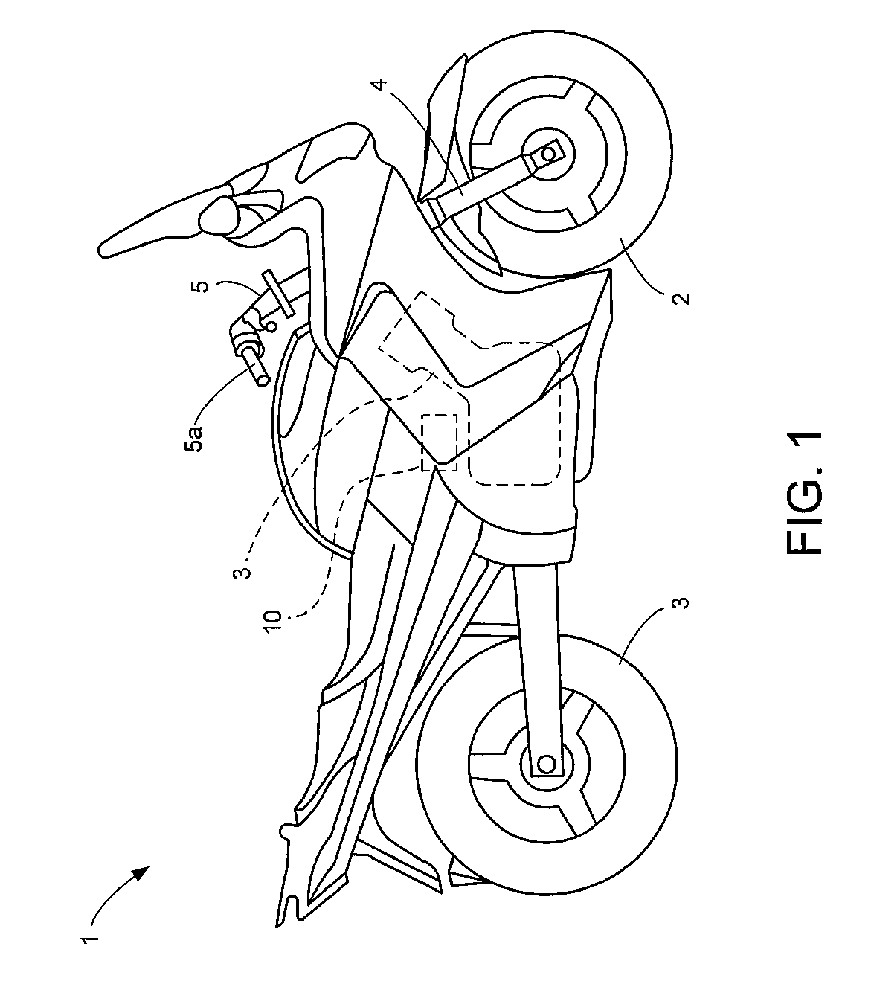
[0022]An embodiment of the present invention is described below with reference to the drawings. FIG. 1 is a side view of a motorcycle 1 provided with a gear change control device 10 according to an exemplary embodiment of the present invention.

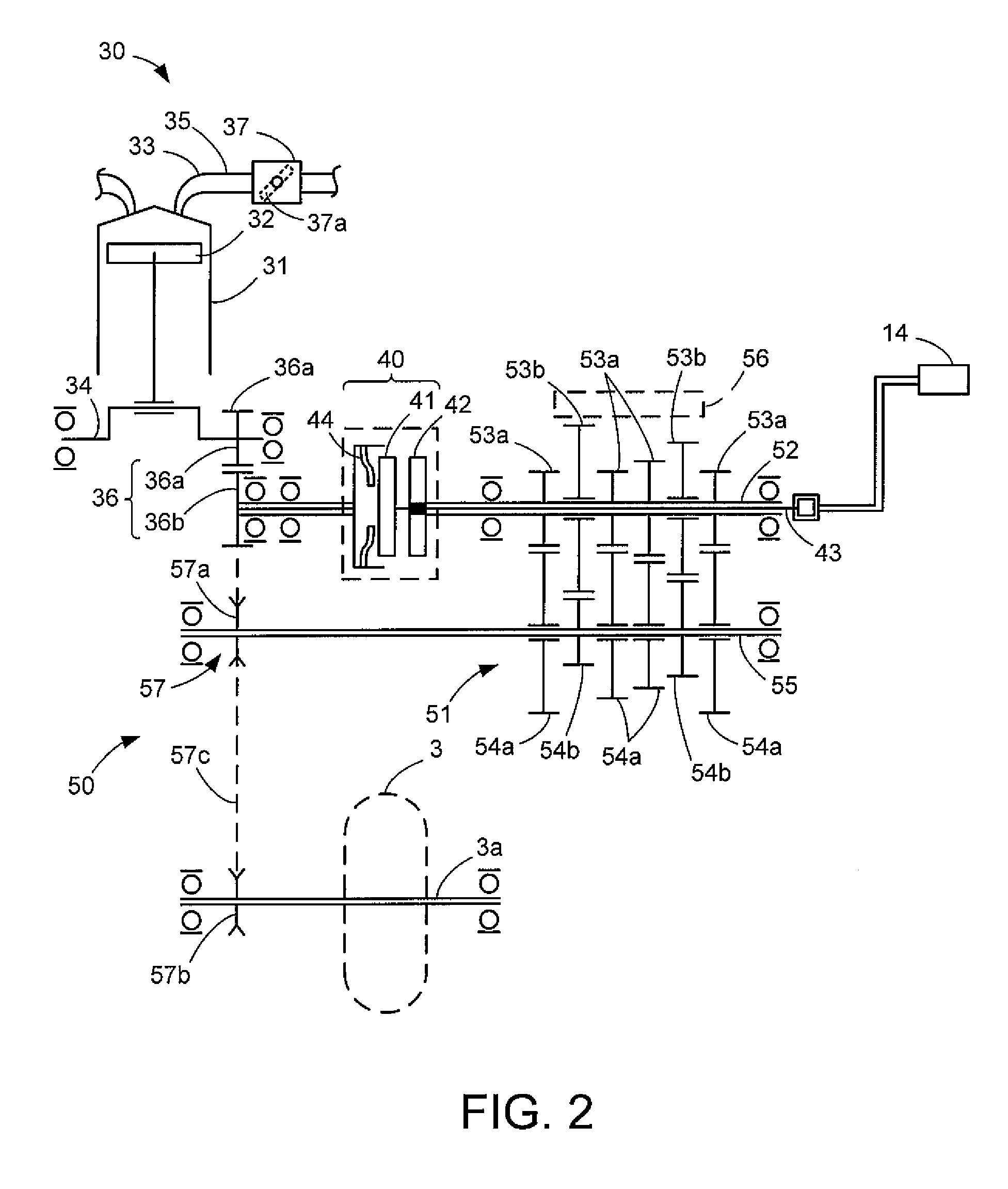
[0023]FIG. 2 is a schematic view of a mechanism located on a torque transmission path of motorcycle 1.

[0024]As shown in FIGS. 1 and 2, in addition to gear change control device 10, motorcycle 1 comprises an engine 30, a primary speed reducing mechanism 36, a clutch 40, a secondary speed reducing mechanism 50, a front wheel 2 and a rear wheel 3.

[0025]Front wheel 2 is supported by a lower end of a front fork 4, and handlebars 5 are connected to the top of front fork 4. An accelerator grip 5a mounted to a right end of handlebars 5 is connected to a throttle valve 37a provided in a throttle body 37 (FIG. 2). Throttle valve 37a is opened according to a rider's accelerator operation, and a certain amount of air, which depends on the opening of throt...


PUM


Abstract

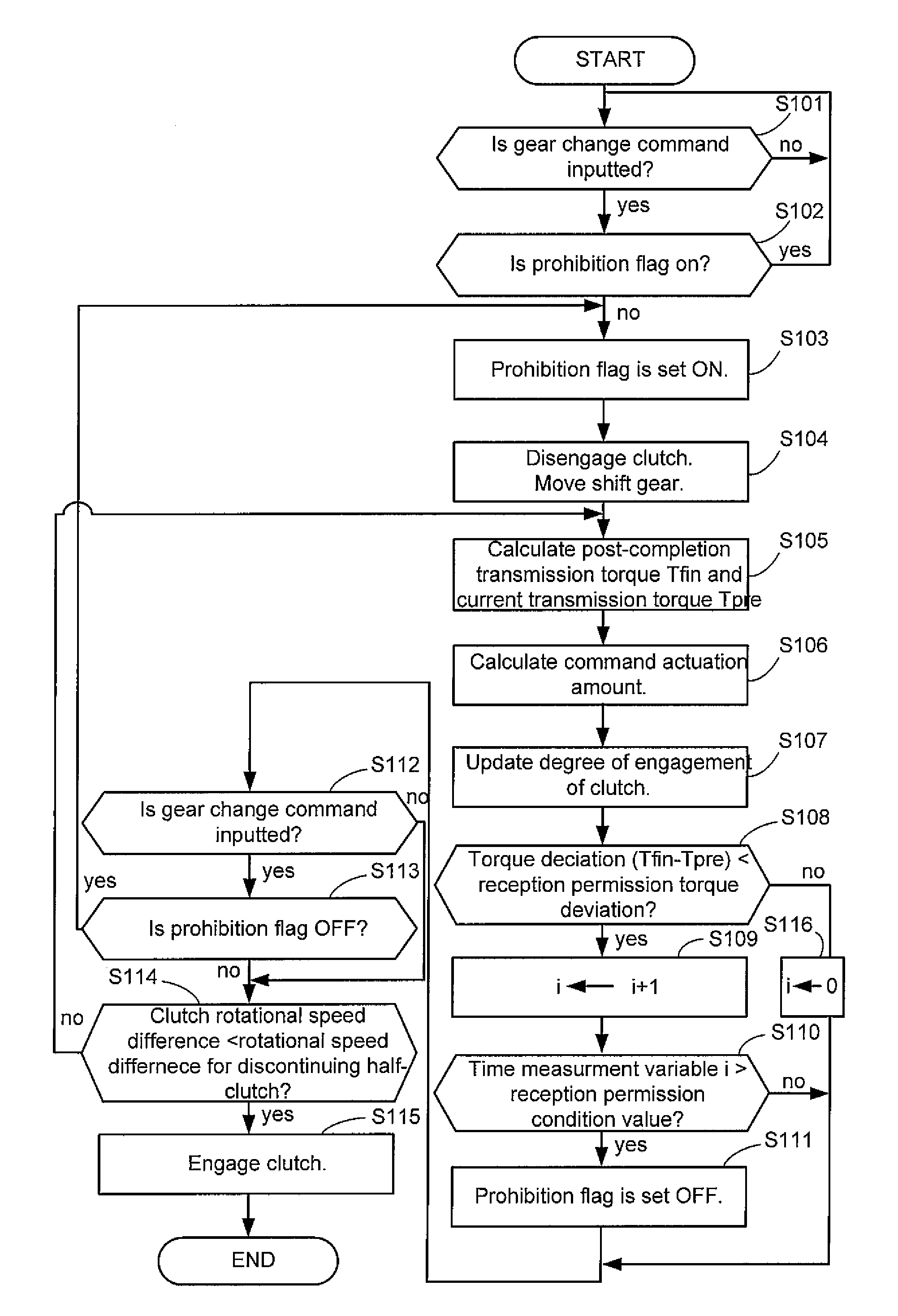
Riding comfort of a vehicle is improved by reducing deceleration and acceleration exceeding the expectation of a rider due to gear changes. A gear change control device calculates current torque being transmitted from a drive-side member of a clutch to a driven-side member of the clutch, and calculates post-completion torque estimated to be transmitted from the drive-side member to the driven-side member after the completion of engagement of the clutch. The gear change control device then controls the degree of engagement of the clutch according to the difference between the current torque and the post-completion torque, and receives a next gear change command according to the difference between the current torque and the post-completion torque.

Description

RELATED APPLICATIONS[0001]This application claims the benefit of priority under 35 USC 119 of Japanese patent application no. 2007-043645, filed on Feb. 23, 2007, and Japanese patent application no. 2007-231135, filed on Sep. 6, 2007, which applications are hereby incorporated by reference in their entireties.BACKGROUND OF THE INVENTION[0002]1. Field of the Invention[0003]The present invention relates to a technique for changing shift gears and engaging and disengaging a clutch using an actuator.[0004]2. Description of Related Art[0005]There have conventionally been vehicles that disengage a clutch and change shift gears by actuating an actuator according to a shift-up or a shift-down operation by a rider. In general, gear change control devices mounted on such vehicles start gradually engaging the clutch after the shift gears have completely been moved (changed).[0006]The driver may occasionally make successive shift-up or shift-down operations in a short time while the vehicle is ...

Claims


Application Information

Patent Timeline
Patent Type & Authority Patents(United States)
IPC IPC(8): B60W10/02B60W10/04
CPCF16D48/06F16H61/0437Y10T477/75F16D2500/30406F16D2500/30421F16D2500/30425F16D2500/3065F16D2500/3144F16D2500/31466F16D2500/70424F16D2500/70488F16H61/682F16H2061/0444F16H2306/14F16H2306/52Y10T477/755Y10T477/78Y10T477/753F16D2500/1117
Inventor MINAMI, KENGOKOSUGI, MAKOTO
Owner YAMAHA MOTOR CO LTD
Learn More