
Device and method for producing a three-dimensional object by means of mask exposure

a three-dimensional object and mask technology, applied in the field of devices, can solve the problems of constant errors and changing homogeneity distribution, and achieve the effects of higher resolution and fine adjustment, higher homogeneity of the system, and high precision

Active Publication Date: 2011-02-22
ENVISIONTEC GMBH DE
View PDF159 Cites 71 Cited by
  • Summary
  • Abstract
  • Description
  • Claims
  • Application Information

AI Technical Summary

Benefits of technology

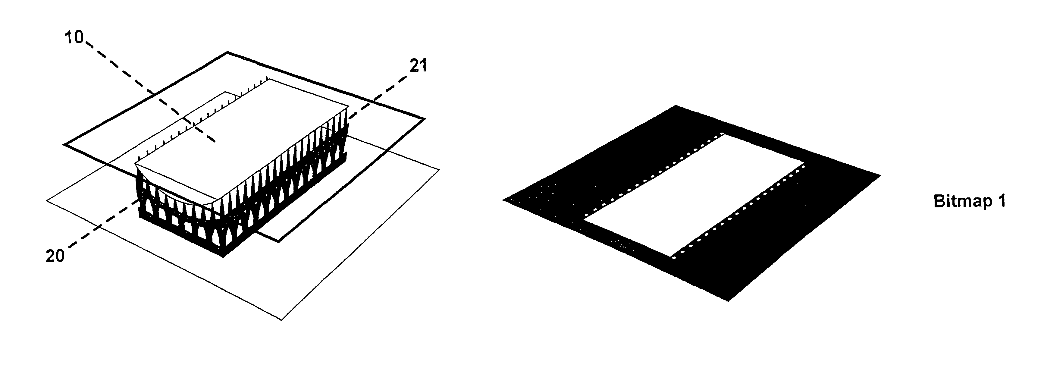
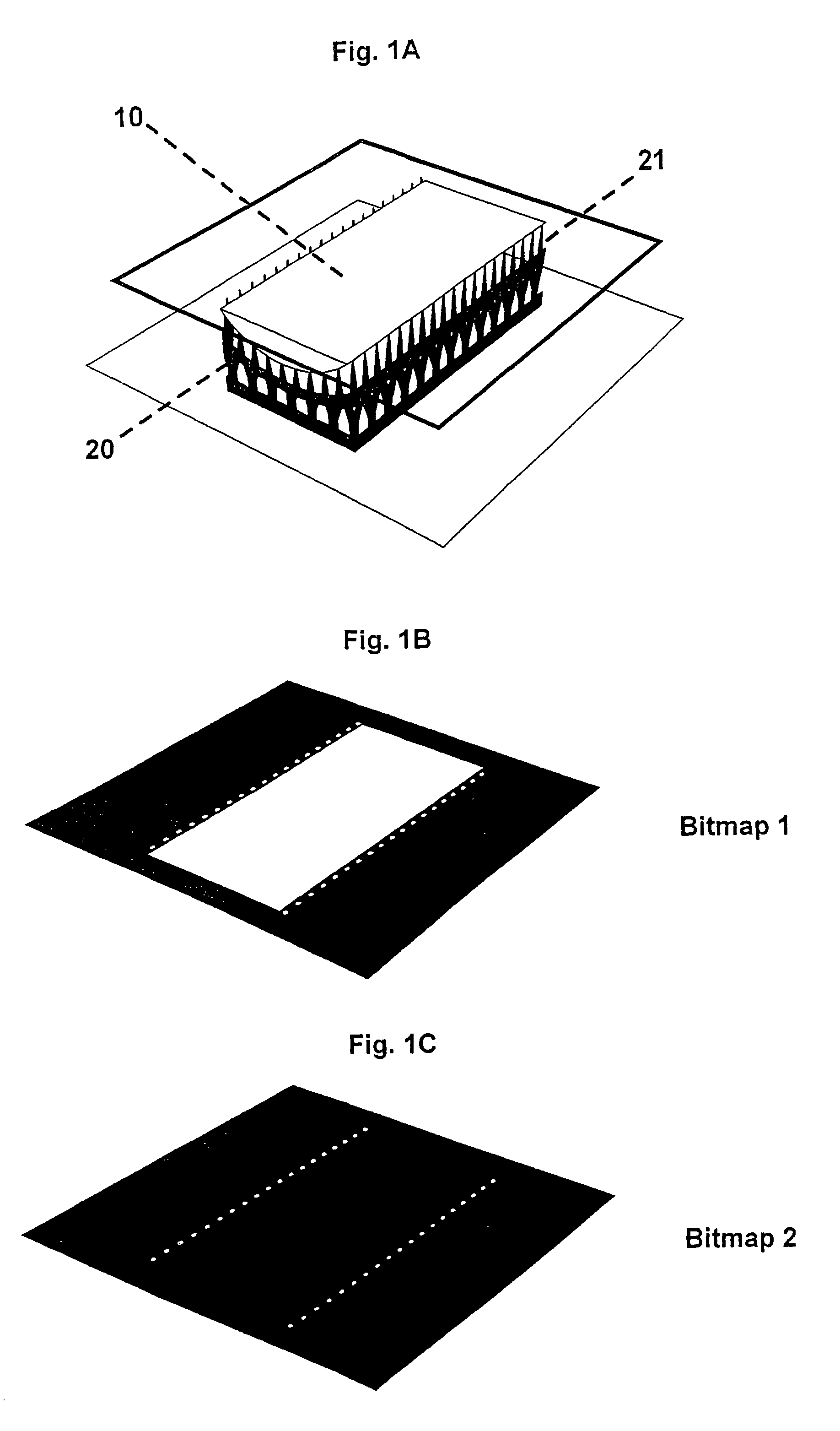
"The present invention provides a device and method for producing a three-dimensional object by solidification of a material solidifiable under the action of electromagnetic radiation. The device includes an imaging unit comprising a predetermined number of discrete imaging elements for energy input and a computer unit, IC, or software implementation for controlling the energy input. The imaging unit composes an image related to a specific cross-sectional area of the three-dimensional object and thus forms a raster mask (bitmap) for solidification. The device can generate at least two masks, including a first overall mask and a partial mask within the overall mask. The method involves solidifying the material under the action of electromagnetic radiation by means of energy input via the imaging unit, where the energy input is controlled using the masks to influence the hardening depth per voxel in the material. The technical effects of the invention include higher precision, higher resolution, fine adjustment, and higher homogeneity of the system."

Problems solved by technology

The disadvantage in projection systems with SLM technology is that the light output distribution over the image surface can be very inhomogeneous (up to 50% absolute), depending ona) the light source used;b) the optical system for coupling the light energy to the SLM; andc) by the vignetting of the projection optics.
The change of the properties of the light source over the service life will result in a variable error and thus in a changing homogeneity distribution.
A constant error is concerned in case of homogeneity deviations caused by the optical system for coupling the light energy to the SLM and the projection optics.

Method used


Image

  • Device and method for producing a three-dimensional object by means of mask exposure
  • Device and method for producing a three-dimensional object by means of mask exposure
  • Device and method for producing a three-dimensional object by means of mask exposure

Examples


Embodiment Construction

[0042]The invention will be described in more detail on the basis of further exemplary embodiments with reference to the attached Figures; however, the invention is by no means limited to the described embodiments and examples and drawings but can instead comprise any variations and modifications within the scope of the claims.

[0043]Device and method according to the invention allow to remove the inhomogeneities in the image level and thus achieve higher precision, higher resolution and fine adjustment.

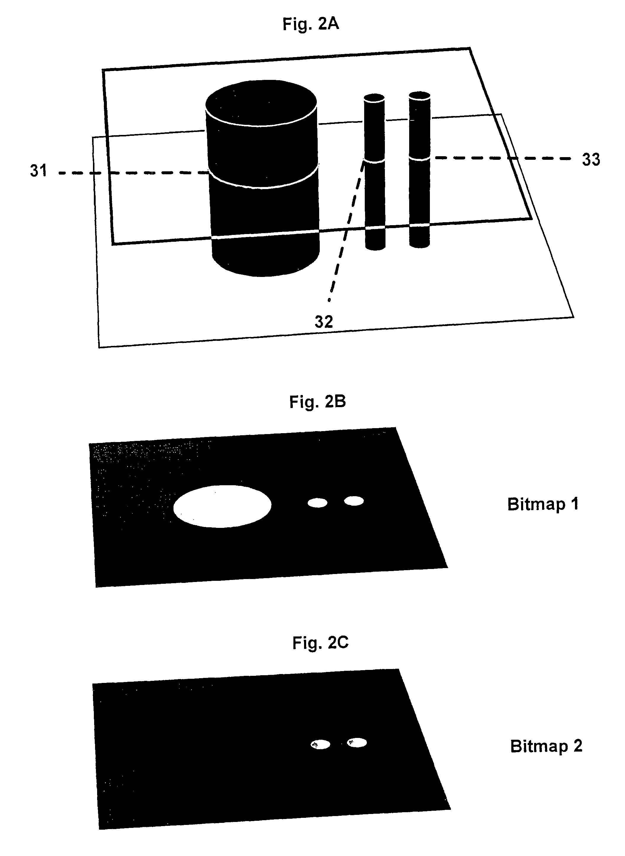
[0044]It is possible with the invention to control, on the one hand, the hardening depth of a voxel in the material to be hardened by means of light output control on a pixel level, and on the other hand, selective portions of the cross-sectional area to be hardened can be specifically overexposed per cross-sectional area without changing the properties of the imaging unit including the light source, by selectively exposing—per building plane / exposure cycle—through one or several succ...


PUM

PropertyMeasurementUnit
thicknessaaaaaaaaaa
thicknessaaaaaaaaaa
depthaaaaaaaaaa

Abstract

The invention describes device and method for producing a three-dimensional object by solidifying a solidifiable material under an action of electromagnetic radiation by means of energy input via an imaging unit comprising a predetermined number of discrete imaging elements (pixels). The energy input related to a specific cross-sectional area of the three-dimensional object is controlled by exposure by means of multiple successive raster masks (bitmaps; e.g. bitmap 1 and bitmap 2 and possibly additional ones). The imaging unit is suitably controllable such that at least two masks can be generated, including a first overall mask covering the cross-sectional area (bitmap 1; with pixel-specific area elements exposing in white light) and a partial mask (bitmap 2; in which only a fraction of the area elements are exposed pixel-specifically with white light) within the overall mask. A voxel matrix may be formed. A hardness depth per voxel (volume pixel) can be specifically and precisely influenced in the solidifyable material.

Description

TECHNICAL FIELD[0001]The invention relates to a device and a method for producing a three-dimensional object by solidification of a solidifiable material under the action of electromagnetic radiation by means of energy input via an imaging unit comprising a specific number of discrete imaging elements (pixels). In particular, this invention relates to devices and methods in which the solidification of the material is based on the exposure by means of a raster mask, with the smallest physical resolution in the mask given by the size of a pixel and the Spatial Light Modulator (SLM) technology being applied for the imaging unit.BACKGROUND ART[0002]The literature specifies highly varying methods for the construction of three-dimensional objects of “light—hardening” photopolymers, cf. “Automated Fabrication—Improving Productivity in Manufacturing” by Marshall Burns, 1993 (ISBN 0-13-119462-3).[0003]Known possibilities are, inter alia, the exposure by[0004]a) multimedia projector[0005]b) L...

Claims


Application Information

Patent Timeline
Patent Type & Authority Patents(United States)
IPC IPC(8): G06F19/00
CPCB29C67/0066G03F7/0037G03F7/2022G03F7/2057B29C71/04B29C67/007B29C67/0062B29C35/0866B33Y50/02G03F7/70291B29C35/0805B33Y50/00B33Y10/00B29C64/124B29C64/135B29C64/129
Inventor JOHN, HENDRIKSCHILLEN, VOLKEREL-SIBLANI, ALI
Owner ENVISIONTEC GMBH DE
Learn More