
Subcritical reactivity measurement method

a nuclear reactor and multiplication factor technology, applied in the field of subcritical reactivity measurement method, can solve the problems of general insensitivity to accurately detect low-level neutron flux emitted in the source range, no direct method for measuring when, and subject to much uncertainty

Active Publication Date: 2011-02-22
WESTINGHOUSE ELECTRIC CORP
View PDF9 Cites 5 Cited by
  • Summary
  • Abstract
  • Description
  • Claims
  • Application Information

AI Technical Summary

Benefits of technology

The invention provides a method for determining the criticality of a nuclear reactor by monitoring the neutron radiation level in the core during a coolant moderator circulation. The method uses a source range detector to monitor the neutron radiation level at different temperatures and removes the non-neutron signal component to obtain a background adjusted neutron radiation level. This level is then used to determine the nearness to criticality. The method allows for the control rod configuration and the concentration of the moderator to remain unchanged between the monitoring of the first and second source range detector signals. The method provides a reliable and accurate means for monitoring the criticality of a nuclear reactor.

Problems solved by technology

Typical fission and ionization chambers are capable of operating at all normal power levels, however, they are generally not sensitive enough to accurately detect low level neutron flux emitted in the source range.
Until relatively recently, there has been no direct method for measuring when criticality will occur from the source range excore detectors.
Therefore, estimating the conditions under which the plant will go critical from the ICRR curve is subject to much uncertainty, but also subject to considerable scrutiny by the Nuclear Regulatory Commission and Institute of Nuclear Power Operations.
However, this method does not address the accuracy of the core reactivity measurement, which is dependent on the accuracy of the measured neutron radiation levels.
The largest neutron measurement error component in a properly operating neutron radiation detector is typically caused by what is commonly called a “background signal”.
This results in errors in the measured core reactivity changes.
To this point in time, there has been no direct method of determining the background signal content in a neutron signal measurement from the typical neutron detectors used in commercial nuclear power facilities.

Method used


Image

  • Subcritical reactivity measurement method
  • Subcritical reactivity measurement method
  • Subcritical reactivity measurement method

Examples


Embodiment Construction

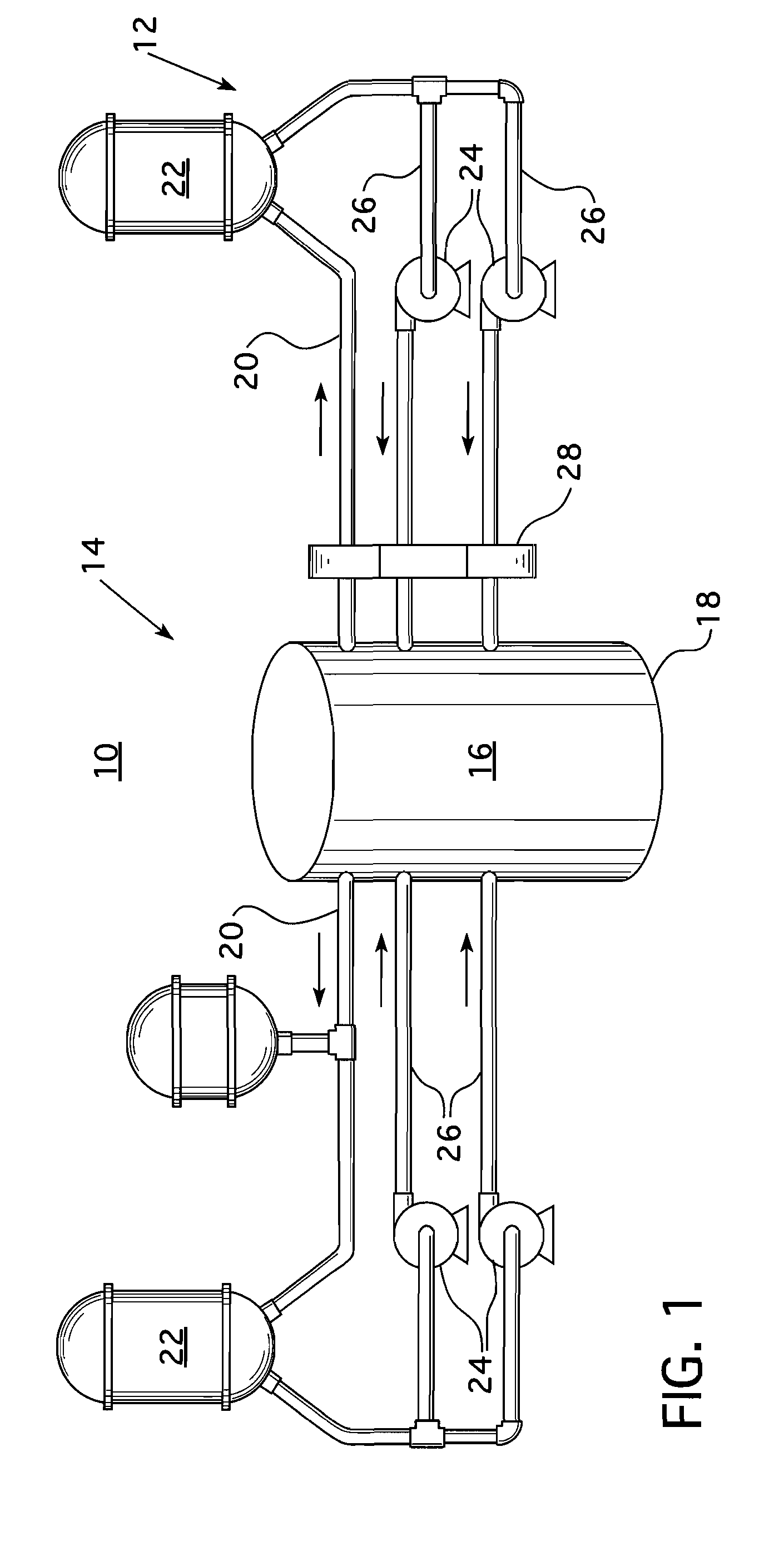
[0017]FIG. 1 illustrates the primary side of a nuclear electric power generating plant 10 in which a nuclear steam supply system 12 supplies steam for driving a turbine generator (not shown) to produce electric power. The nuclear steam supply system 12 has a pressurized water reactor 14 which includes a reactor core 16 housed within a pressure vessel 18. Fission reactions within the reactor core 16 generate heat, which is absorbed by a reactor coolant, like water, which is passed through the core. The heated coolant is circulated through hot leg piping 20 to a steam generator 22. Reactor coolant is returned to the reactor 14 from the steam generator 22 by a reactor coolant pump 24 from the cold leg piping 26. Typically, a pressurized water reactor has at least two and often three or four steam generators 22 each supplied with heated coolant through a hot leg 20, forming with the cold leg 26 and the reactor coolant pump 24, a primary loop. Each primary loop supplies steam to the turb...


PUM


Abstract

A method of determining the spatially corrected inverse count ratio (SCICR) used to determine reactor criticality, which subtracts a background noise signal from the source range detector output. The method monitors the source range detector signal at two different core temperature levels during a transient portion of the detector output as the power output of the reactor is increased in the source range. This information is employed to analytically determine the background noise signal, which is then subtracted from the detector outputs to obtain the SCICR reactivity measurement.

Description

BACKGROUND OF THE INVENTION[0001]1. Field of the Invention[0002]This invention relates to a method for measuring the subcritical neutron multiplication factor, Keff of a nuclear reactor, and more particularly, to a method for determining all reactivity changes that occur while a core of a nuclear reactor is subcritical.[0003]2. Related Art[0004]In a pressurized water reactor power generating system, heat is generated within the core of a pressure vessel by a fission chain reaction occurring in a plurality of fuel rods supported within the core. The fuel rods are maintained in space relationship within fuel assemblies with the space between fuel rods forming coolant channels through which borated water flows. Hydrogen within the coolant water moderates the neutrons emitted from enriched uranium within the fuel to increase the number of nuclear reactions and thus increase the efficiency of the process. Control rod guide thimbles are interspersed within the fuel assemblies in place of ...

Claims


Application Information

Patent Timeline
Patent Type & Authority Patents(United States)
IPC IPC(8): G21C17/00
CPCG01T1/00G21C19/40G21C17/104Y02E30/30
Inventor HEIBEL, MICHAEL D.SEBASTIANI, PATRICK J.ANDERSON, STANWOOD L.
Owner WESTINGHOUSE ELECTRIC CORP
Learn More