Liquid application device, inkjet recording apparatus, and method of controlling liquid application device
a liquid application device and liquid recording technology, applied in the direction of measuring apparatus components, instruments, printing, etc., can solve the problems of reducing causing clogging of the nozzle, and generating many constraints, so as to reduce the viscosity of the treatment liquid and reduce the viscosity of the liquid
- Summary
- Abstract
- Description
- Claims
- Application Information
AI Technical Summary
Benefits of technology
Problems solved by technology
Method used
Image
Examples
first embodiment
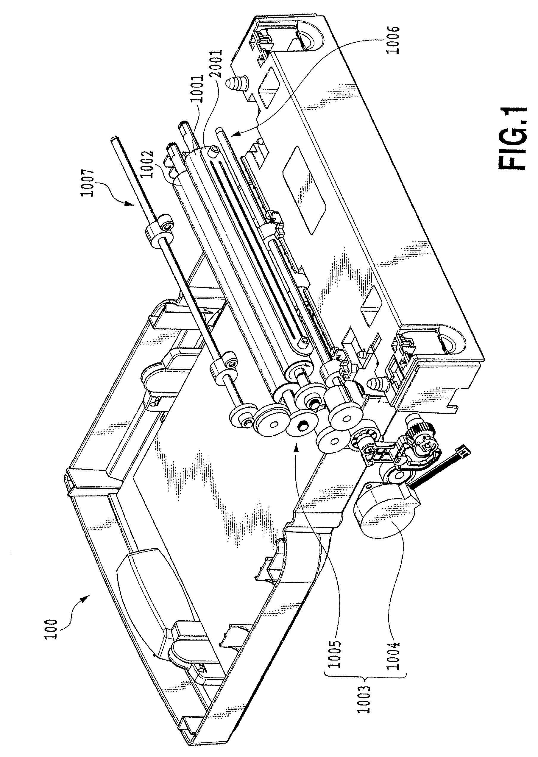
[0071]FIG. 1 is a perspective view showing an overall structure of the embodiment of a liquid application device 100 of the present invention. The liquid application device 100 shown here generally includes liquid application means for applying a predetermined application liquid to a medium (hereinafter also referred to as the application medium) which is an object to which the liquid is applied and liquid supply means for supplying the application liquid to the liquid application means.
[0072]The liquid application means includes a cylindrical application roller 1001, a cylindrical counter roller (a medium supporting member) 1002 placed so as to face the application roller 1001 and a roller drive mechanism 1003 driving the application roller 1001. The roller drive mechanism 1003 includes a roller drive motor 1004 and a power transmission mechanism 1005 including a gear train for transmitting the driving force of the roller drive motor 1004 to the application roller 1001.
[0073]The li...
second embodiment
[0151]FIG. 20 is a look-up table for deciding the number of preliminary rotations (preliminary rotational time) in this embodiment. The preprocessing operation in this embodiment aims at discharging the thickened matter of the application liquid remaining on the application roller and in the liquid retention member and dust adhering thereto when the device is left unused for a long time when ΔT is 24 hours or more. Namely, this is the control method for collecting the application liquid at least once after the fixed number of preliminary rotations are performed.
[0152]FIG. 16 is a flow chart showing a processing procedure of preprocessing in this embodiment.
[0153]In FIG. 16, processing in steps S41, S42 and S45 to S47 are the same as processing of steps S21, S22 and S23 to S25 shown in FIG. 14, respectively.
[0154]In this embodiment, information on a lapse of time, which indicates a lapse of time between the end time of the previous collection and the start time of the current applica...
third embodiment
[0164]In the first and second embodiments, the preprocessing operation is performed before the start of the current application, after the previous collection is ended and the predetermined time has passed. On the other hands, in this embodiment, the preprocessing operation is controlled according to the lapse of time between the end time of the previous application operation (stop time of the rotation of the application roller for the application operation) before previous collection operation and the start time of the current application operation (start time of the rotation of the application roller for the application operation).
[0165]FIG. 18 is a flow chart showing a processing procedure of preprocessing in this embodiment.
[0166]In step S3 in FIG. 13, when the operation of the pump 3007 is started, the previous stop time information, which indicates the time when the application roller 1001 is stopped, is read from the nonvolatile memory 4012 in step S61. In addition to this, c...
PUM
 Abstract
Description
Claims
Application Information
 - R&D
- Intellectual Property
- Life Sciences
- Materials
- Tech Scout
- Unparalleled Data Quality
- Higher Quality Content
- 60% Fewer Hallucinations
Browse by: Latest US Patents, China's latest patents, Technical Efficacy Thesaurus, Application Domain, Technology Topic, Popular Technical Reports.
© 2025 PatSnap. All rights reserved.Legal|Privacy policy|Modern Slavery Act Transparency Statement|Sitemap|About US| Contact US: help@patsnap.com


