GPS positioning method and GPS reception apparatus

a positioning method and reception apparatus technology, applied in the direction of instruments, digital transmission, transmission, etc., can solve the problems of affecting the accuracy of the time information, the inability to obtain time information longer than 1 millisecond, and the inability to accurately determine the time information

Inactive Publication Date: 2007-09-04
SONY CORP
View PDF5 Cites 14 Cited by
  • Summary
  • Abstract
  • Description
  • Claims
  • Application Information

AI Technical Summary

Benefits of technology

[0025]It is an object of the present invention to provide a GPS positioning method and a GPS reception apparatus by which time required, for example, until time synchronism is established after power is made available to a GPS receiver can be shortened.

Problems solved by technology

Therefore, there is the possibility that the chip frequency of the PN code may be displaced between the satellite signal and the signal of the GPS receiver.
However, only if synchronism of the C / A code is established, only time information shorter than 1 millisecond is obtained, but time information longer than 1 millisecond is not obtained.
Since comparatively much time is normally required for the frequency search, there is a problem that much time is required until positioning arithmetic calculation is performed finally to measure the position of the GPS receiver at present.
Where the conventional time synchronization method described above is used, there is a problem that information of the preamble and the TOW for acquiring time information longer than 1 millisecond is obtained in a unit of a subframe, that is, only once in 6 seconds.
The time of more than 6 seconds makes an obstacle if it is tried to shorten the time required until positioning arithmetic operation is started after power is made available.
Further, where it is intended to incorporate the GPS positioning system in a portable apparatus, although power saving is demanded, such power saving cannot be achieved sufficiently because the prior art requires much time until positioning arithmetic operation is started as described above.

Method used


Image

  • GPS positioning method and GPS reception apparatus
  • GPS positioning method and GPS reception apparatus
  • GPS positioning method and GPS reception apparatus

Examples


Embodiment Construction

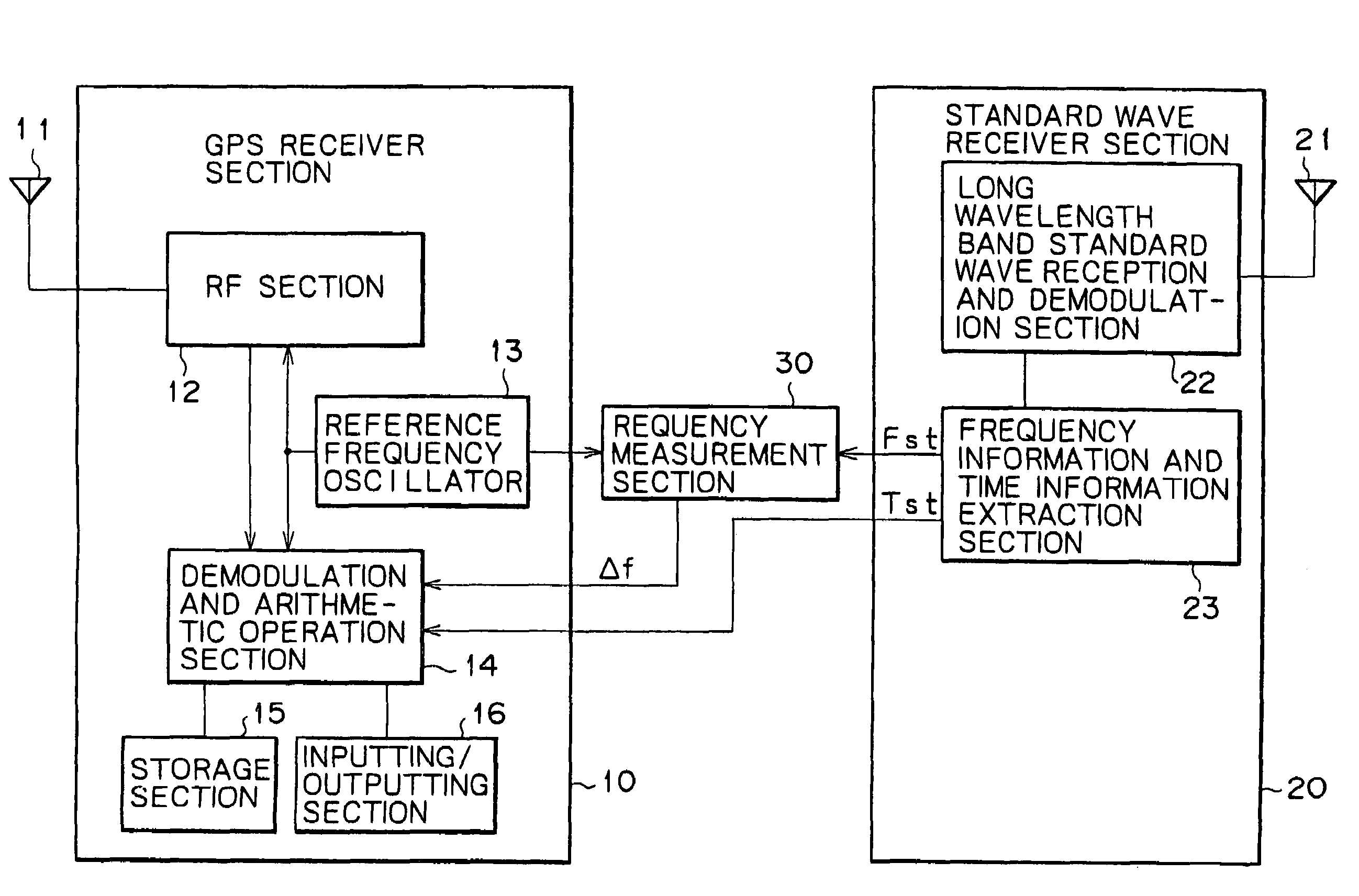
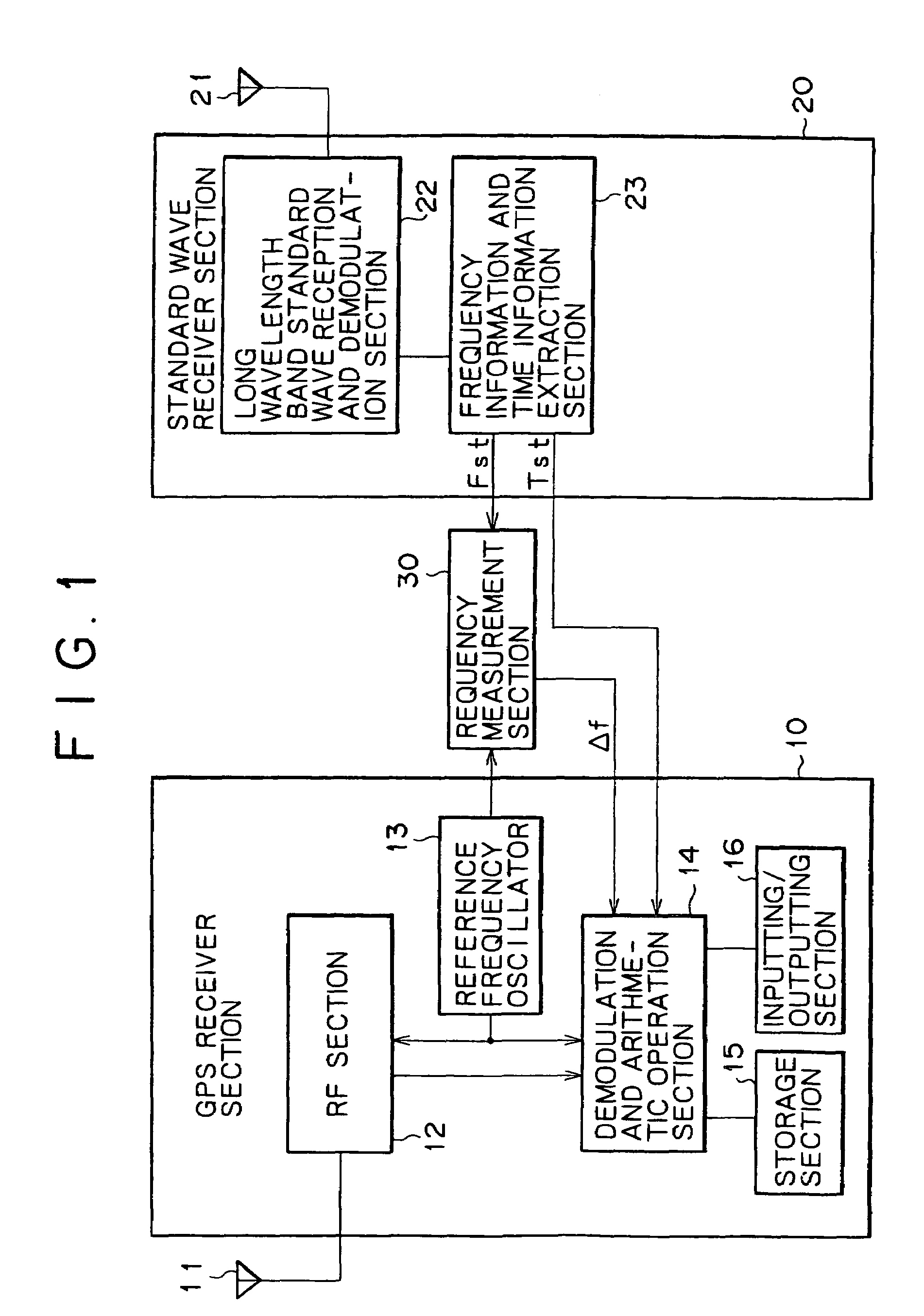
[0056]Referring first to FIG. 1, there is shown a system construction of a GPS reception apparatus of the present invention to which a GPS positioning method of the present invention is applied. The GPS reception apparatus includes a GPS receiver section 10, a standard wave receiver section 20, and a frequency measurement section 30.

[0057]The GPS receiver section 10 includes an antenna section 11 which receives a GPS satellite signal and so forth and supplies the reception signal to a radio frequency processing section 12. The radio frequency processing section 12 is hereinafter referred to simply as RF section 12. The RF section 12 uses a frequency signal from a reference frequency oscillator 13 to convert the frequency of the reception signal into a signal of an intermediate frequency of several MHz to several tens MHz and outputs the intermediate frequency signal to a demodulation and arithmetic operation section 14. The demodulation and arithmetic operation section 14 establishe...


PUM


Abstract

A GPS positioning method is disclosed which can shorten the time required until positioning arithmetic operation is started after power is made available. An oscillation frequency of a reference frequency oscillator used in a GPS receiver section or a frequency variation of the oscillation frequency is measured using high precision frequency information provided by a standard wave. A result of the measurement is utilized to catch a signal from a GPS satellite. Further, a synchronization timing of a spread code of the spread spectrum signal from the satellite is detected to detect a small time component for time synchronization. After synchronization of the spread code is completed, a time of the boundary of one period of the spread code is detected from time information provided by a standard wave, and a time component greater than the small time component for time synchronization is detected based on the time of the boundary. Time synchronism is established using the detected small time component and the time component greater than the small time component.

Description

BACKGROUND OF THE INVENTION[0001]This invention relates to a GPS (Global Positioning System) positioning method and a GPS reception apparatus to which the method is applied.[0002]In a GPS system wherein a plurality of artificial satellites called GPS satellites are utilized to measure the position of a moving body, a spread spectrum modulation system is used as a modulation system for signal waves from the artificial satellites. For example, in a consumer GPS receiver, spread spectrum signal waves called C / A codes (Course Acquisition Codes) from GPS satellites (Navistar's) are received to perform positioning arithmetic operation.[0003]The C / A code is formed from a code of a PN (Pseudo random Noise) series whose transmission signal rate is 1.023 MHz, for example, a Gold code. The code of the PN series repetitively appears with one period thereof provided by 1,023 chips (accordingly, one period=1 millisecond) as seen from FIG. 13A.[0004]The code of the PN series of the C / A code is dif...

Claims


Application Information

Patent Timeline
Patent Type & Authority Patents(United States)
IPC IPC(8): H04B1/00G01S1/00G01S5/04G01S19/25G01S19/37H04B1/707H04B1/7075H04L7/00
CPCG01S19/23G01S19/24G01S19/25G01S19/34G01S19/37G01S5/04
Inventor HASEGAWA, KOJIWAKAMORI, MIKIOKANETSUNA, HARUO
Owner SONY CORP
Why Eureka
Try Eureka