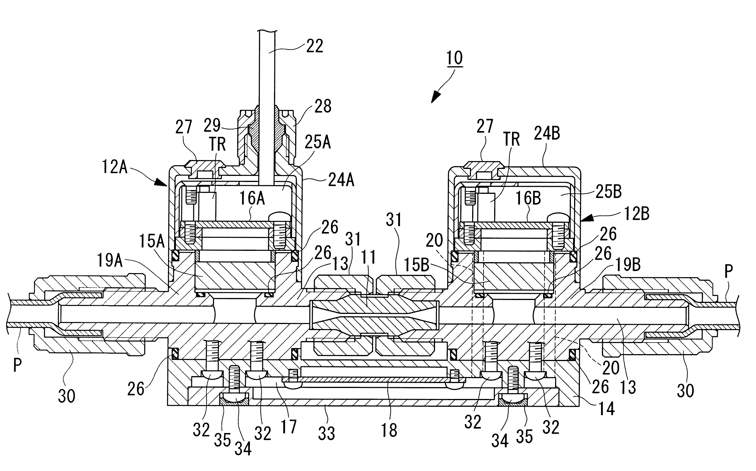
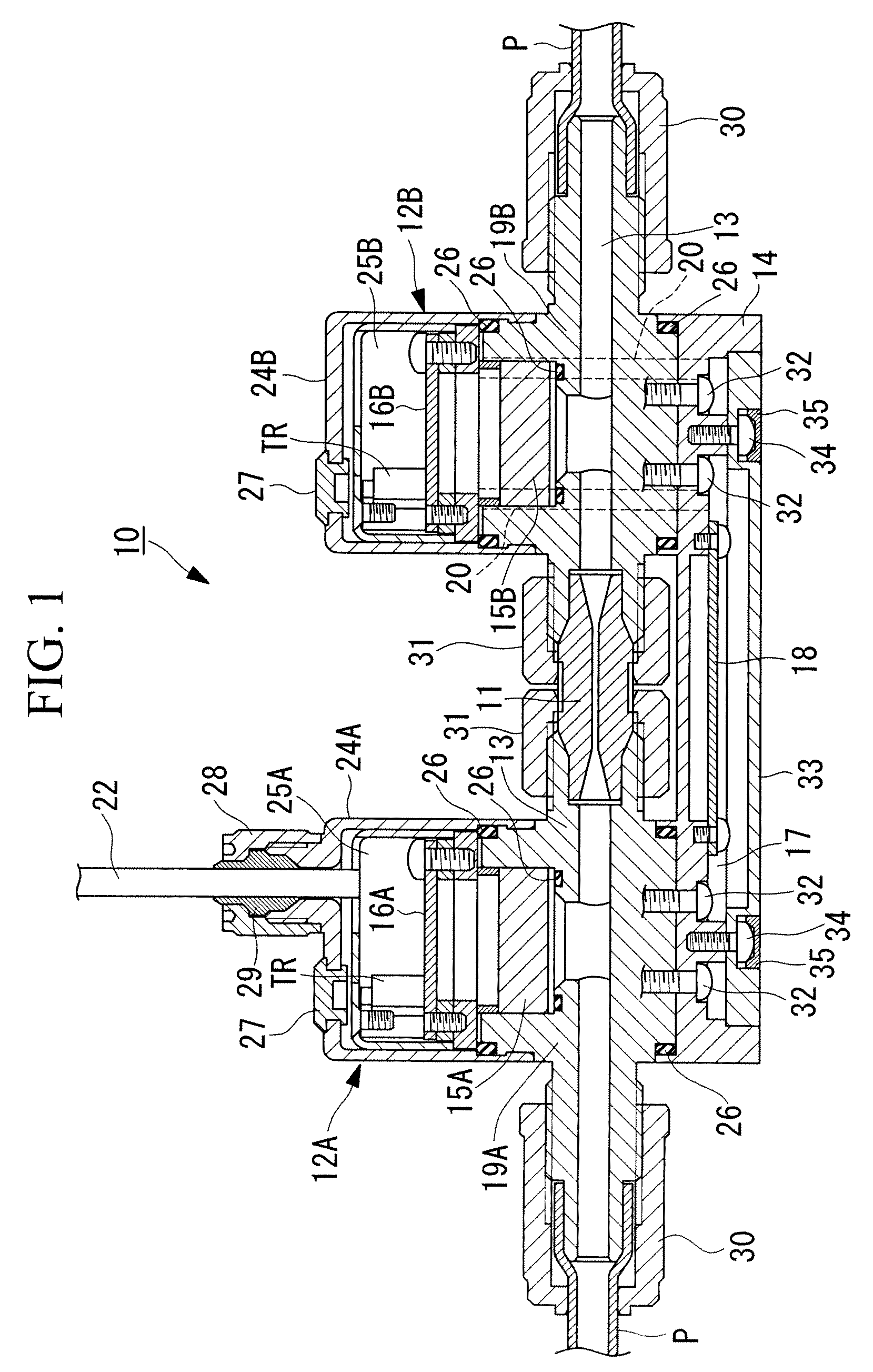
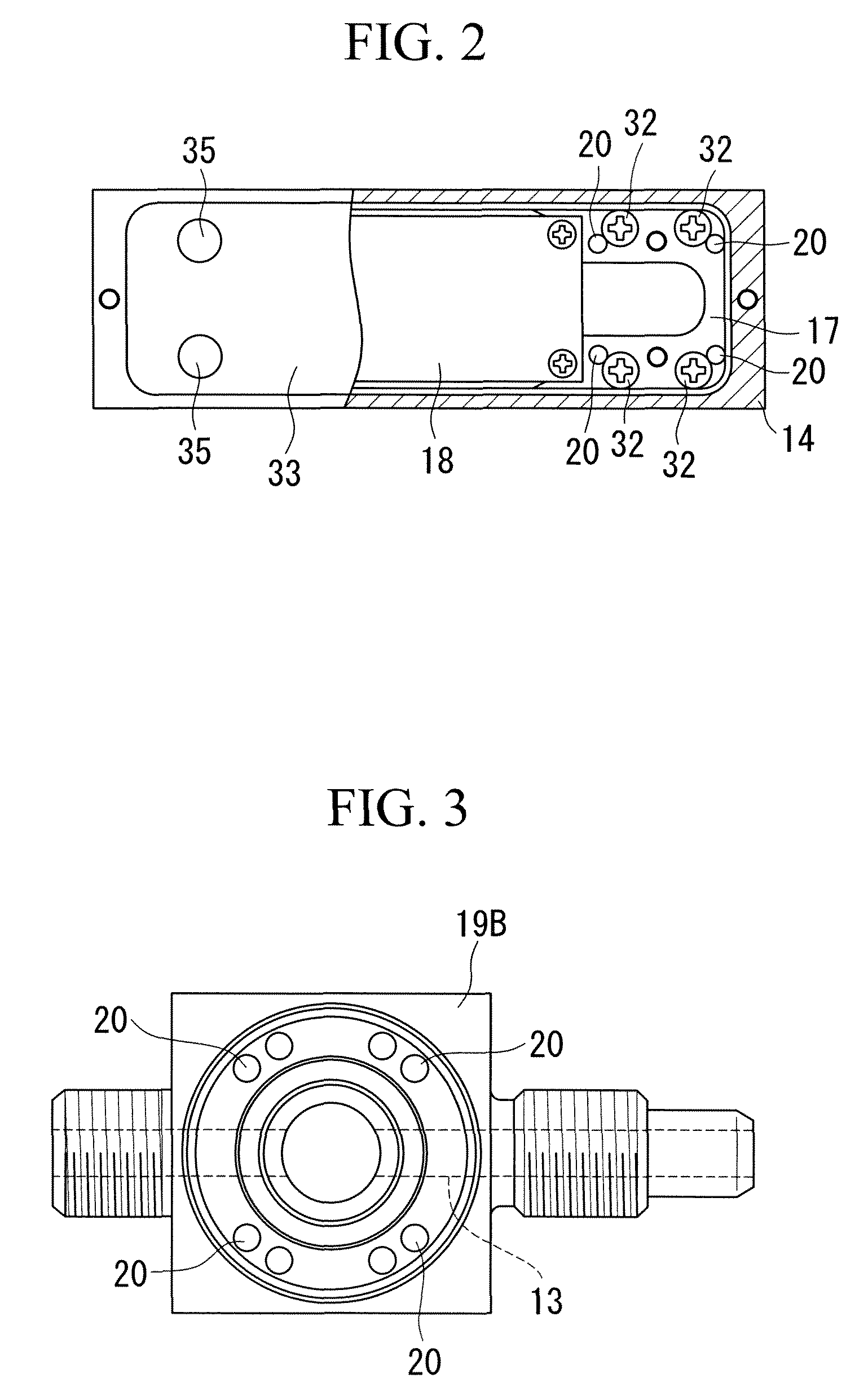
Differential-pressure flow meter having a main control board in a space in a base member
a technology of control board, which is applied in the direction of volume/mass flow measurement, measurement devices, instruments, etc., can solve the problems of complex connections and allocation of installation space, and achieve the effect of reducing the size of the differential pressure flow meter itself, reducing the cross-sectional area, and effectively utilizing the thickness of the member
- Summary
- Abstract
- Description
- Claims
- Application Information
AI Technical Summary
Benefits of technology
Problems solved by technology
Method used
Image
Examples
first embodiment
[0075]An orifice member 11A of a first embodiment shown in FIGS. 7 and 8 integrally includes a tube portion 41 which has one end connected to the first pressure sensor 12A and the other end connected to the second pressure sensor 12B and in which a flow channel is formed so as to connect the first and second pressure sensors 12A and 12B and an orifice 42 provided in the tube portion 41.
[0076]In the example shown, the orifice member 11A has a substantially cylindrical shape with only the center 41a of the tube portion 41 in the longitudinal direction being solid. A hole 41b of the orifice flow channel extending from one end to the other end of the tube portion 41 is formed in the center 41a in the longitudinal direction so as to be coaxial with the axis of the tube portion 41. The center 41a in the longitudinal direction thus forms the orifice 42.
[0077]That is, the tube portion 41 and the orifice 42 are formed as a single member, and the orifice member 11A has no seam that can cause ...
second embodiment
[0096]A second embodiment of the orifice member 11 will now be described with reference to FIGS. 11 and 12.
[0097]In FIG. 11, an orifice member 11C of this embodiment differs in the structure for connection to the first and second pressure sensors 12A and 12B. Members similar or identical to those of the embodiment described above are indicated by the same reference numerals, and a detailed description thereof will be omitted.
[0098]In FIG. 12, the orifice member 11C is mainly characterized in that the tube portion 41 and the sleeves 36 of the orifice member 11A shown in the first embodiment are replaced with a tube portion 41A having flexible ends, inserted in the orifice cap nuts 31, at which large-diameter portions 43 are formed. The large-diameter portions 43 are larger in diameter than the other portion and are configured to receive the connection ends of the first and second pressure sensors 12A and 12B inside, as described below. The engagement flanges 31b of the orifice cap nu...
third embodiment
[0105]A third embodiment of the orifice member 11 according to the present invention will now be described with reference to FIGS. 13 and 14.
[0106]An orifice member 11D of this embodiment differs from the orifice member 11 shown in the first embodiment in the structure for connection to the first and second pressure sensors 12A and 12B. Members similar or identical to those of the first embodiment are indicated by the same reference numerals, and a detailed description thereof will be omitted.
[0107]The orifice member 11D is mainly characterized in that the tube portion 41 and the sleeves 36 of the orifice member 11 shown in the first embodiment are replaced with a tube portion 41B having rigid ends, inserted in the orifice cap nuts 31, at which large-diameter portions 44 are provided in the outer circumferential surfaces. The engagement flanges 31b of the orifice cap nuts 31 engage with the large-diameter portions 44.
[0108]Like the sleeves 36 shown in the first embodiment, the abutm...
PUM
 Abstract
Description
Claims
Application Information
 - R&D
- Intellectual Property
- Life Sciences
- Materials
- Tech Scout
- Unparalleled Data Quality
- Higher Quality Content
- 60% Fewer Hallucinations
Browse by: Latest US Patents, China's latest patents, Technical Efficacy Thesaurus, Application Domain, Technology Topic, Popular Technical Reports.
© 2025 PatSnap. All rights reserved.Legal|Privacy policy|Modern Slavery Act Transparency Statement|Sitemap|About US| Contact US: help@patsnap.com


