
Phosphor and manufacturing method therefore, and light emission device using the phosphor

a technology of light emission device and phosphor, which is applied in the direction of discharge tube/lamp details, discharge tube luminescnet screen, transportation and packaging, etc., can solve the problems of short life span, unsatisfactory color rendering properties of white light obtained, and deterioration of color rendering properties, etc., to improve emission intensity and luminance, improve the effect of durability against heat and water, and stable manufacture of white led illumination

Inactive Publication Date: 2011-02-15
MITSUBISHI CHEM CORP
View PDF10 Cites 28 Cited by
  • Summary
  • Abstract
  • Description
  • Claims
  • Application Information

AI Technical Summary

Benefits of technology

The solution provides white LED illumination with improved color rendering properties and high luminance, maintaining stability and durability against heat and water, and allows for the production of various emission colors with excellent emission efficiency.

Problems solved by technology

At present, a discharge type fluorescent lamp and an incandescent bulb used as the illumination device involve problems that a harmful substance such as mercury is contained, and life span is short.
However, the problem of the white LED illumination is that the emission on the long-wavelength side of visible light range, specifically the emission of red color component is insufficient, and therefore, only slightly bluish white emission can be obtained, and a slightly reddish white emission like an electric bulb can not be obtained, thereby deteriorating in the color rendering properties.
However, the red phosphor out of the phosphors of three colors has a sharp emission spectrum, while the phosphors of other colors have broad emission spectra, thereby involving the problem that the color rendering properties of the white light obtained is unsatisfactory, and emission characteristic at a high temperature is deteriorated.
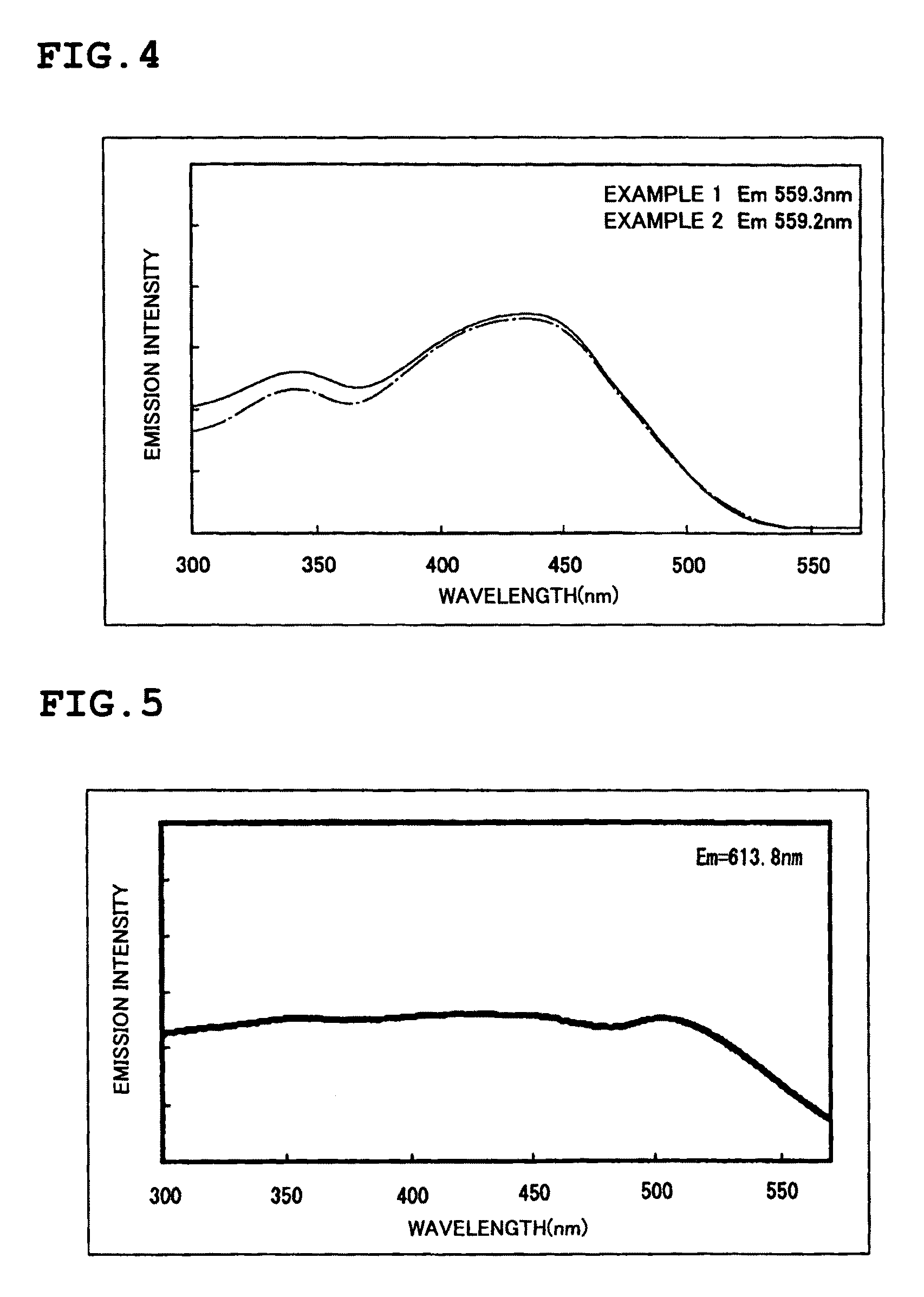
First, the problem involved in the yellow phosphor YAG:Ce is explained by using FIG. 25. FIG. 25 is a graph showing the emission intensity (relative intensity) taken on the ordinate axis and the wavelength of an excitation light taken on the abscissa axis, and showing an excitation spectrum obtained by measuring an intensity of the light having the wavelength of 559.2 nm emitting light when the YAG:Ce is excited by an excitation light having the wavelength of 300 to 570 nm.
However, since the excitation band is narrow, the emission wavelength of the blue LED is changed due to variation in manufacturing the blue LED when excited by the blue light of the blue LED, then if the emission wavelength is deviated from the range of an optimal excitation band of the YAG:Ce phosphor, disruption of balance between the blue color and yellow color emission intensity occurs.
Such a situation involves the problem that color tone of the white light obtained by synthesizing the blue light and the yellow light is changed.
Therefore, the problem involved therein is that a sufficient emission can not be obtained, and the high luminance white LED illumination can not be obtained.
Out of such phosphors, the problem is that a sulfide phosphor is significantly deteriorated in emission intensity, when heat is applied thereto, and further has no water-resisting property.
In addition, an oxide phosphor does not have a good efficient excitation band in a broad range of the wavelength in the vicinity of the near ultraviolet / ultraviolet.
Therefore, the problem involved therein is that when the variation in emission wavelength occurs due to by variation in manufacturing the near ultraviolet / ultraviolet LED, the emission wavelength of the near ultraviolet / ultraviolet LED is deviated from the optimal excitation range, thereby disrupting the balance in emission intensity among the red color, green color, and blue color, resulting in the change of the color tone of the white light.

Method used


Image

  • Phosphor and manufacturing method therefore, and light emission device using the phosphor
  • Phosphor and manufacturing method therefore, and light emission device using the phosphor
  • Phosphor and manufacturing method therefore, and light emission device using the phosphor

Examples


example

Example 1

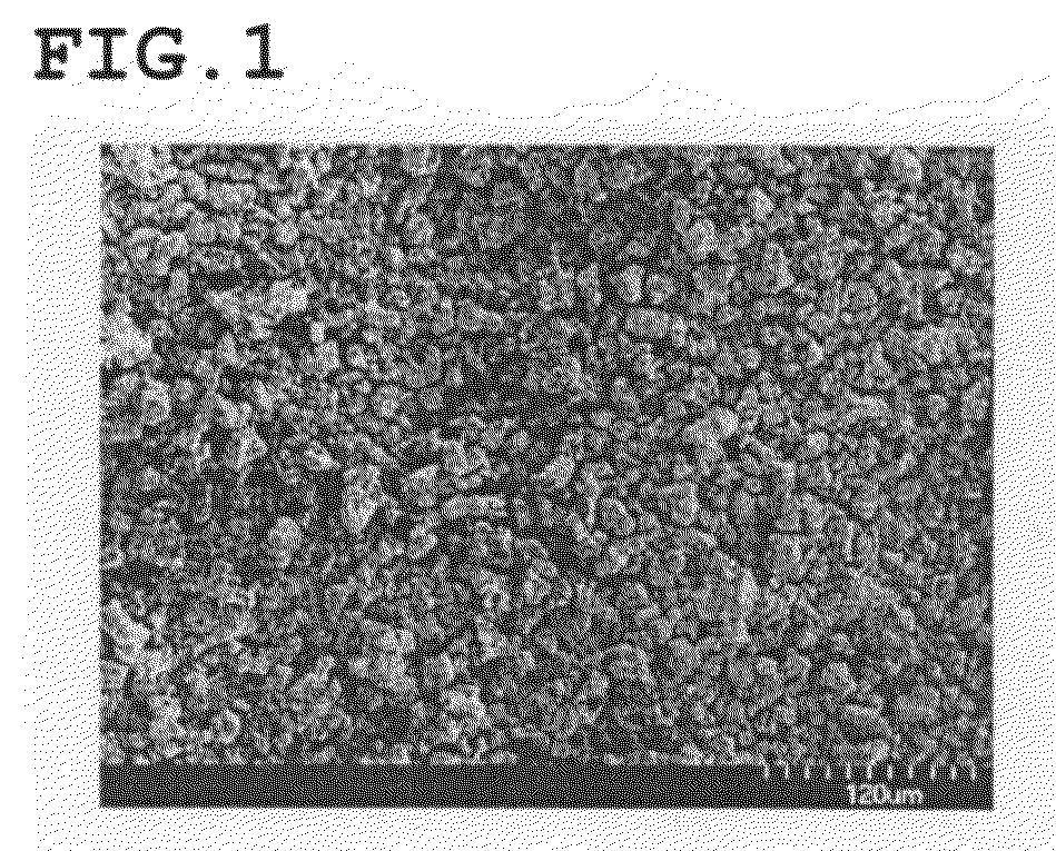
[0205]Commercially available SrCO3(3N), AlN(3N), Si3N4(3N), and CeO2(3N) were prepared, and among the raw materials, 0.970 mol of SrCO3, 1.0 mol of AlN, 4.5 / 3 mol of Si3N4, and 0.030 mol of CeO2 were weighed and mixed by using a mortar in an atmospheric air. The raw material thus mixed was put in a BN crucible, then temperature is increased to 1800° C. with an in-furnace pressure of 0.05 MPa set at 15° C. / min, retained and fired at 1800° C. for three hours, and then cooled from 1800° C. to 200° C. for one hour. Thereafter, the firing sample thus fired was crushed to a proper particle size by using the mortar in the atmospheric air, and the phosphor of the example 1 of the composition formula expressed by Sr2Al2Si9O2N14:Ce (where Ce / (Sr+Ce)=0.030) was obtained. A result of a composition analysis of the powdery phosphor thus obtained is shown in table 1-2, and an SEM photograph of the powdery phosphor (250 times) is shown in FIG. 1.

[0206]The result of the composition analysis...

example 2

[0215]In the example 2, the phosphor of the example 2 is manufactured in the same way as the example 1, other than the molar ratio of each element of the example 1 is set at Sr:Al:Si:Ce=0.970:1:5:0.030.

[0216]The commercially available SrCO3(3N), AlN(3N), Si3N4(3N), CeO2(3N) were prepared, and each raw material was measured in 0.970 mol of SrCO3, 1.0 mol of AlN, 5.0 / 3 mol of Si3N4, and 0.030 mol of CeO2, so that the molar ratio of each element was set at Sr:Al:Si:Ce=0.970:1:5:0.030, and the raw materials thus measured was mixed in the atmosphere by using the mortar. The raw materials thus mixed was put in the crucible, and the temperature was increased to 1800° C. at 15° C. / min, with in-furnace pressure of 0.05 MPa, in a nitrogen atmosphere (flow state), and in this condition, the raw materials were retained and fired for 3 hours at 1800° C., then cooled from 1800° C. to 200° C. for 1 hour. Thereafter, a fired sample was pulverized in an atmospheric air to obtain a suitable particle ...

example 3

[0223]In the example 3, the phosphor of the example 3 was manufactured in the same way as the example 1, other than replacing Ce with Eu, as the activator, in the phosphor expressed by the composition formula Sr2Al2Si9O2N14:Ce (where Ce / (Sr+Ce)=0.030) of the phosphor of the example 1. The molar ratio of each element was expressed by Sr:Al:Si:Eu=0.970:1:4.5:0.030, and each raw material was measured in 0.970 mol of SrCO3, 1.0 mol of AlN, 4.5 / 3 mol of Si3N4, and 0.030 / 2 mol of Eu2O3. In the same way as the example 1, the analysis result of the powdery phosphor thus obtained is shown in table 1-2.

[0224]

TABLE 1-2AVERAGESPECIFICPARTICLESURFACECOMPOSITIONSrAlSiONCeEuOTHERSSIZEAREAFORMULA(wt %)(wt %)(wt %)(wt %)(wt %)(wt %)(wt %)(wt %)D50 (μm)(m2 / g)EXAMPLE 1Sr2Al2Si9O2N14:Ce24.87.0732.22.2530.51.231.9817.500.285EXAMPLE 2Sr3Al3Si15O3N23:Ce23.76.1133.62.1130.51.102.8816.850.302EXAMPLE 3Sr2Al2Si9O2N14:Eu24.57.1332.31.8328.11.324.8217.270.291

[0225]The analysis result of the composition of the p...


PUM

PropertyMeasurementUnit
molar ratioaaaaaaaaaa
wavelengthaaaaaaaaaa

Abstract

To provide a phosphor having an emission spectrum with a broad peak in a range from green color to yellow color, having a broad and flat excitation band capable of using lights of broad range from near ultraviolet / ultraviolet to blue lights as excitation lights, and having excellent emission efficiency and luminance. The problem is solved by providing the phosphor expressed by a general composition formula MmAaBbOoNn:Z (where element M is one or more kinds of elements having bivalent valency, element A is one or more kinds of elements having tervalent valency, element B is one or more kinds of elements having tetravalent valency, O is oxygen, N is nitrogen, and element Z is one or more kinds of elements acting as the activator), satisfying 4.0<(a+b) / m<7.0, a / m=0.5, b / a>2.5, n>o, n=2 / 3m+a+4 / 3b−2 / 3o, and having an emission spectrum with a peak wavelength of 500 nm to 650 nm when excited by light in a wavelength range from 300 nm to 500 nm.

Description

TECHNICAL FIELD OF THE INVENTION[0001]The present invention relates to a phosphor containing nitrogen used for a cathode-ray tube (CRT), a display such as a field emission display (FED) and a plasma display (PDP), and an illumination device such as a fluorescent lamp and a fluorescent display tube, and an illumination device such as a crystal liquid back light and a method of manufacturing therefore, and also to a light emission device such as a white LED illumination in which a phosphor mixture, a phosphor sheet, a semiconductor light emitting element (LED) and this phosphor are combined.BACKGROUND OF THE INVENTION[0002]At present, a discharge type fluorescent lamp and an incandescent bulb used as the illumination device involve problems that a harmful substance such as mercury is contained, and life span is short. However, in recent years, a high luminescence LED emitting light of near ultraviolet / ultraviolet to blue color has been developed in sequence, and the white LED illumina...

Claims


Application Information

Patent Timeline
Patent Type & Authority Patents(United States)
IPC IPC(8): H01L33/00C09K11/64H01L33/50
CPCC09K11/7721C09K11/7734H01L33/502Y10T428/2982H01L2224/48247H01L2224/48091H01L2924/00014H01L2924/181C09K11/77218C09K11/77348H01L2924/00012
Inventor NAGATOMI, AKIRASAKANE, KENJI
Owner MITSUBISHI CHEM CORP
Learn More