Inertial sensor
a sensor and sensor technology, applied in the field ofinertial sensors, can solve the problems of deteriorating detection performance, insufficient software arithmetic processing, and insufficient detection accuracy, and achieve the effect of accurately setting the detection axis of the sensor, improving workability, and avoiding deterioration of detection performance of the detection elemen
- Summary
- Abstract
- Description
- Claims
- Application Information
AI Technical Summary
Benefits of technology
Problems solved by technology
Method used
Image
Examples
first embodiment
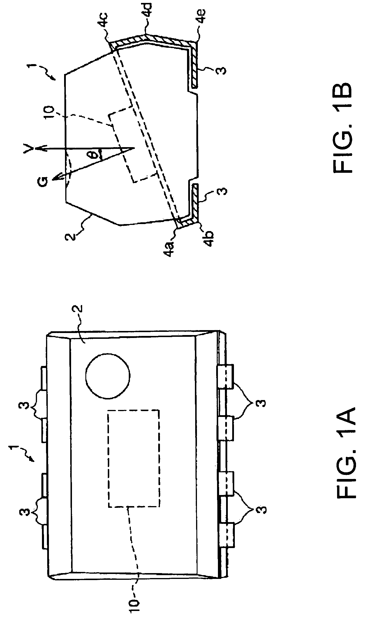
[0070]FIGS. 1A and 1B are schematic views illustrating the structure of a gyro sensor device of the invention. FIG. 1A is the top view. FIG. 1B is the side view.
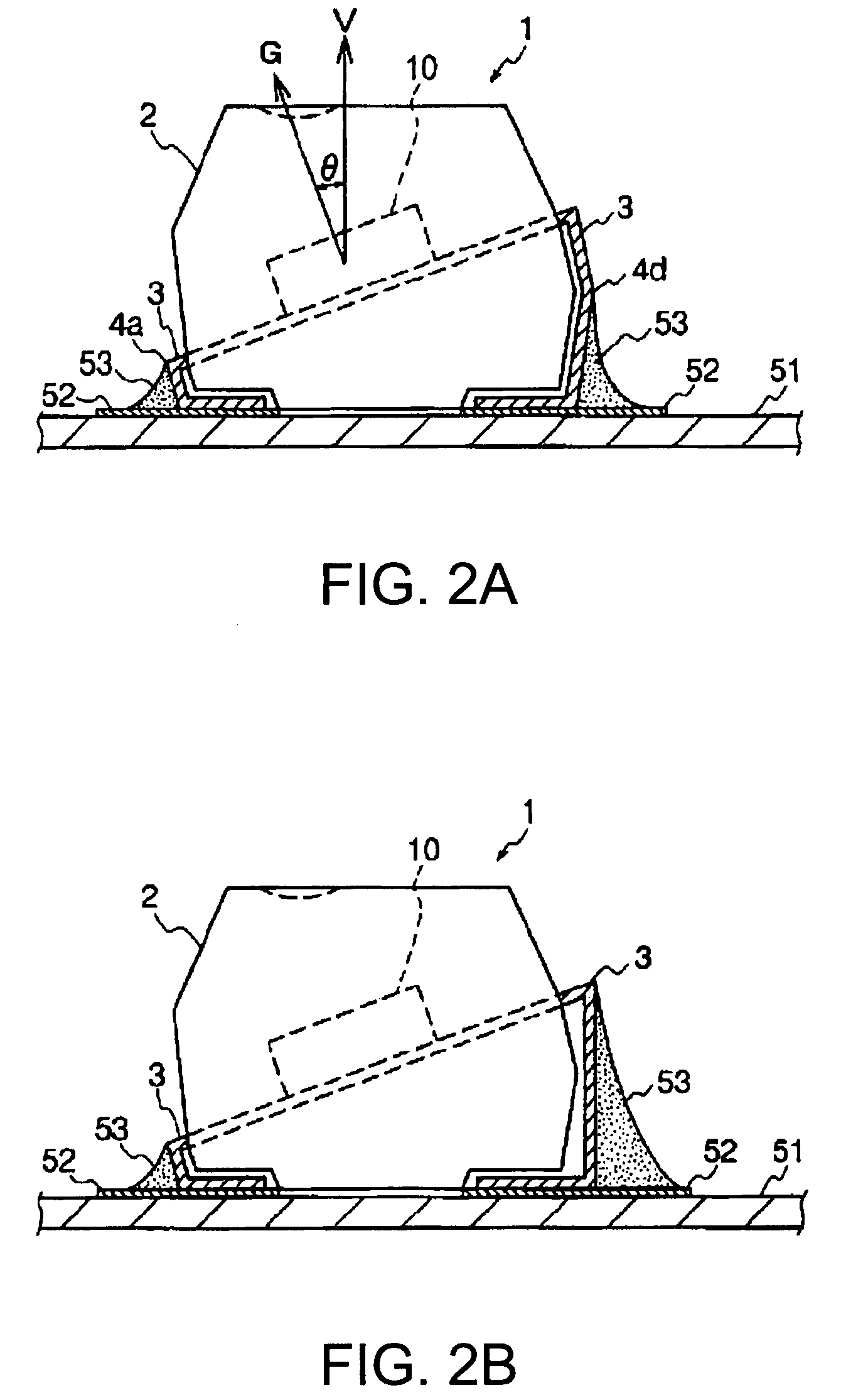
[0071]In a gyro sensor device 1 shown in FIGS. 1A and 1B, a gyro sensor 10 is sealed with a resin part 2, formed by a molding compound such as resin, so that the angular velocity detection axis G (detection axis G) of the gyro sensor 10 is tilted by an angle θ with respect to the perpendicular line V of the upper surface of the gyro sensor device 1. From both the long sides of the resin part 2, a plurality of lead terminals extends outside.
[0072]Here, the upper surface and a mounting side surface (the other surface opposite to the upper surface) of the gyro sensor device 1 are in parallel with each other. The lead terminals 3 are electrically connected to the gyro sensor 10 inside the resin part 2. The lead terminals 3 exposed from the resin part 2 at a position close to its bottom surface are bent inside at bending parts 4a...
second embodiment
[0120]FIG. 5 is a schematic view illustrating the structure of a gyro sensor device according to the invention.
[0121]In a gyro sensor device 20 shown in FIG. 5, the gyro sensor 10 is sealed with the resin part 2 so that the detection axis G of the gyro sensor 10 is tilted by the angle θ with respect to the perpendicular line of a mount surface on which the gyro sensor device 20 is mounted.
[0122]In this case, also, the lead terminal 3 extends outside from both the long sides of the resin part 2 in a plurality of numbers. The gyro sensor 10 is tilted by the angle θ with respect to the upper surface of the gyro sensor device 1 by supporting with the lead terminal 3, bent at the bending parts 6e, 6f, and 6g in the resin part 2. In the structure, the length between the bending parts 6a and 6b is nearly equal to the length between the bending parts 6c and 6d. This structure can prevent the occurrence of errors in the tilt angle of the gyro sensor device 20 when it is mounted to the mount ...
third embodiment
[0128]FIG. 7 is a schematic view illustrating the structure of a gyro sensor device according to the invention.
[0129]In a gyro sensor device 30 shown in FIG. 7, the gyro sensor 10 is sealed with the resin part 2 so that the gyro sensor 10 is tilted by the angle θ with respect to the vertical direction of a mount surface on which the gyro sensor device 30 is mounted.
[0130]In this case, also, the lead terminal 3 extends outside from both the long sides of the resin part 2 in a plurality of numbers. The gyro sensor 10 is tilted by the angle θ with respect to the upper surface of the gyro sensor device 30 by supporting with the lead terminal 3, bent in a step shape at the bending parts 7e, 7f, 7g, 7h, 7i, 7j, 7k and 7l in the resin part 2. In the structure, the length between the bending parts 7a and 7b is nearly equal to the length between the bending parts 7c and 7d. This structure can prevent the occurrence of errors in the tilt angle of the gyro sensor device 30 when it is mounted t...
PUM
| Property | Measurement | Unit |
|---|---|---|
| tilt angle | aaaaa | aaaaa |
| physical quantity | aaaaa | aaaaa |
| flexibility | aaaaa | aaaaa |
Abstract
Description
Claims
Application Information
 - R&D
- Intellectual Property
- Life Sciences
- Materials
- Tech Scout
- Unparalleled Data Quality
- Higher Quality Content
- 60% Fewer Hallucinations
Browse by: Latest US Patents, China's latest patents, Technical Efficacy Thesaurus, Application Domain, Technology Topic, Popular Technical Reports.
© 2025 PatSnap. All rights reserved.Legal|Privacy policy|Modern Slavery Act Transparency Statement|Sitemap|About US| Contact US: help@patsnap.com


