
Adjustable fisherman seat assembly and associated method

a fisherman seat and assembly technology, applied in the field of boat seat assembly, can solve the problems of inability to operate smoothly, swivel mechanism often breaks or jams, and the combination of swivel-slide boat seat does not operate reliably under the conditions encountered, and achieves the effect of preventing arcuate movement of the platform

Inactive Publication Date: 2011-02-08
SNYDER CARL
View PDF12 Cites 16 Cited by
  • Summary
  • Abstract
  • Description
  • Claims
  • Application Information

AI Technical Summary

Benefits of technology

Such a linear-to-rotational movement allows the user to pivot the seat section in clockwise and counter clockwise direction while maintaining one hand permanently positioned on the fishing rod. A free hand of the user is grasped about the actuating arm during operating conditions. Therefore, the present invention provides an ergonomic and simply mechanism that allows the user to advantageously bias the seat section without loosing control of the fishing rod.
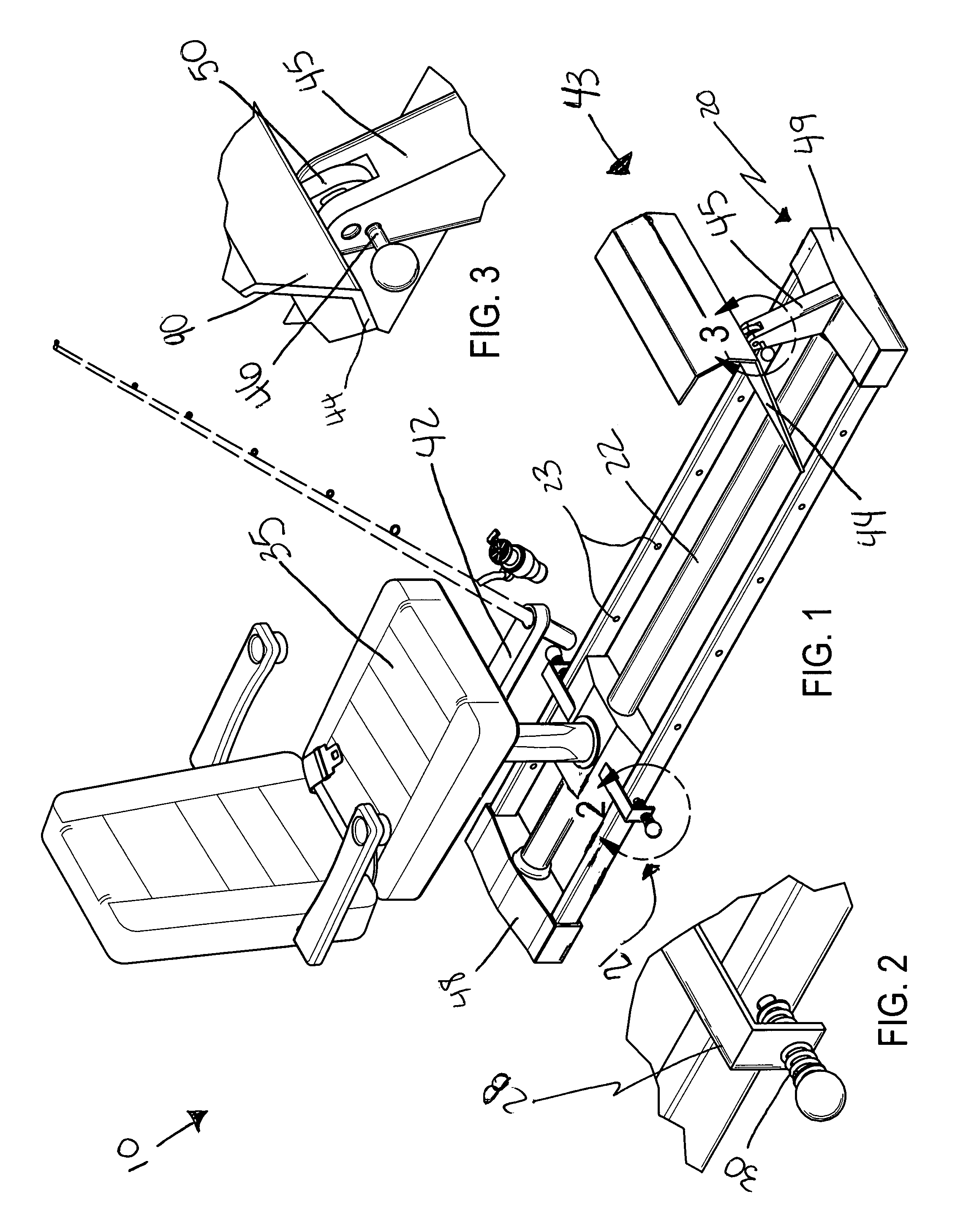
The assembly further includes a mechanism for advantageously supporting user feet above the base member and at an elevated angle offset from the horizontal plane such that the user feet conveniently remain distally positioned in front of the user during operating conditions. Such a user feet supporting mechanism includes a platform that has a planar bottom portion and an arcuate upper portion monolithically formed therewith. A support stand is anchored to the distal end of the base member and is statically engaged with the base member. Such a platform is effectively provided with a finger extending downwardly therefrom and pivotally attached to a top end of the support stand such that the platform is freely articulated along an arcuate path distally spaced from the seat section. A locking pin is threadably mated with the top end of the support stand and the finger respectively to thereby advantageously prohibit arcuate movement of the platform during operating conditions.
The method further includes the steps of: providing a linear shaft that extends parallel to the longitudinal length of the base member and has opposed ends connected to the proximal and distal ends of the base member respectively; providing a pair of linear slots formed within the bottom housing that are defined orthogonal to the shaft; providing a bore formed with the bottom housing with the shaft passing through the bore; removably positioning first and second linear arms within the linear slots respectively; statically coupling a bracket to the bottom housing and the first and second linear arms respectively; and positioning first and second pairs of spring members about the first and second linear arms respectively. The first and second pairs of spring members are oppositely seated on inner and outer sides of respective lower portions of the bracket such that the first and second arms are automatically returned to a locked position after they are laterally displaced out from the slots respectively.
The method further includes the steps of: supporting user feet above the base member at an elevated angle offset from the horizontal plane such that the user feet remain distally positioned in front of the user during operating conditions. The method further includes the steps of providing a platform that has a planar bottom portion and an arcuate upper portion monolithically formed therewith; anchoring a support stand to the distal end of the base member that is statically engaged with the base member; providing a finger extending downwardly from the platform that is pivotally attached to a top end of the support stand such that the platform is freely articulated along an arcuate path distally spaced from the seat section; and threadably mating a locking pin with the top end of the support stand and the finger respectively to thereby prohibit arcuate movement of the platform during operating conditions.

Problems solved by technology

Although there are known boat seats that are both swivable and slidably adjustable, in general it has been found that these combined swivel-slide boat seats do not operate reliably under the conditions encountered aboard a boat.
After a while the swivel mechanism will often break or jam up and not operate smoothly.
Also, the environmental conditions under which a boat seat is used oftentimes is not compatible with continuous smooth and reliable operation of a conventional ball bearing swivel mechanism, and more so when used in conjunction with a slide adjustment.
Unfortunately, this prior art example includes swivel plates which allow the seat to swivel, thereby requiring a fisherman to maneuver about the waist in a physically demanding manner.
Unfortunately, this prior art example cannot be adjusted in angular positioning, plus or minus 20 degrees from horizontal, to suit the preference of the occupant.
Unfortunately, this prior art example includes a pivotal connection that requires a user to control the seat using the waist and thereby demanding excessive physical exertion.

Method used


Image

  • Adjustable fisherman seat assembly and associated method
  • Adjustable fisherman seat assembly and associated method
  • Adjustable fisherman seat assembly and associated method

Examples


Embodiment Construction

The present invention will now be described more fully hereinafter with reference to the accompanying drawings, in which a preferred embodiment of the invention is shown. This invention may, however, be embodied in many different forms and should not be construed as limited to the embodiment set forth herein. Rather, this embodiment is provided so that this application will be thorough and complete, and will fully convey the true scope of the invention to those skilled in the art. Like numbers refer to like elements throughout the figures.

The assembly is referred to generally in FIGS. 1-15 by the reference numeral 10 and is intended to protect an adjustable fisherman seat assembly. It should be understood that the assembly 10 may be used on many different types of water vessels and should not be limited in use to only those types of water vessels described herein.

Referring initially to FIG. 1, the adjustable fisherman seat assembly conveniently includes an elongated base member 20 t...


PUM


Abstract

An adjustable fisherman seat assembly includes an elongated base member and a seat section. A mechanism for linearly displacing the seat includes: a linear shaft; a pair of linear slots; a bore; first and second linear arms; a bracket; and first and second pairs of spring members. A mechanism for adjustably pivoting the seat includes: a bar; a support plate; a rod; a toothed wheel; an elbow lever; an actuating arm; and a pawl. A fishing rod holder is statically coupled to the adjustably pivoting mechanism. A mechanism for supporting user feet includes a platform and a support stand. Such a platform has a finger extending downwardly and a locking pin. A plurality of independently compressible spring members is nested within the seat section.

Description

STATEMENT REGARDING FEDERALLY SPONSORED RESEARCH OR DEVELOPMENTNot Applicable.REFERENCE TO A MICROFICHE APPENDIXNot Applicable.BACKGROUND OF THE INVENTION1. Technical FieldThis invention relates to seat assemblies for water vessels and, more particularly, to an adjustable fisherman seat assembly for use on a water vessel.2. Prior ArtThere are a number of commercially available swiveled boat seats. Conventionally, the swivel comprises a number of ball bearings suitably and rotatably resting in suitable races or recesses between adjoining disks. One of the disks is normally coupled to the boat seat and the other secured in some fashion to the boat deck, either directly or through a support post or pillar, so that the user can swing the seat around as he or she desires. There are also a number of commercially available slides for boat seats. Although there are known boat seats that are both swivable and slidably adjustable, in general it has been found that these combined swivel-slide ...

Claims


Application Information

Patent Timeline
IPC IPC(8): B63B17/00
CPCB63B29/04B63B2029/043
Inventor SNYDER, CARL
Owner SNYDER CARL
Learn More