
Speaker device

a speaker device and terminal technology, applied in the direction of deaf-aid sets, electrical transducers, transducer details, etc., can solve problems such as sensitivity degradation, and achieve the effects of maintaining the ventilation performance of the speaker device, facilitating configuration, and facilitating expansion of the terminal setting spa

Inactive Publication Date: 2011-02-01
PIONEER CORP +1
View PDF14 Cites 8 Cited by
  • Summary
  • Abstract
  • Description
  • Claims
  • Application Information

AI Technical Summary

Benefits of technology

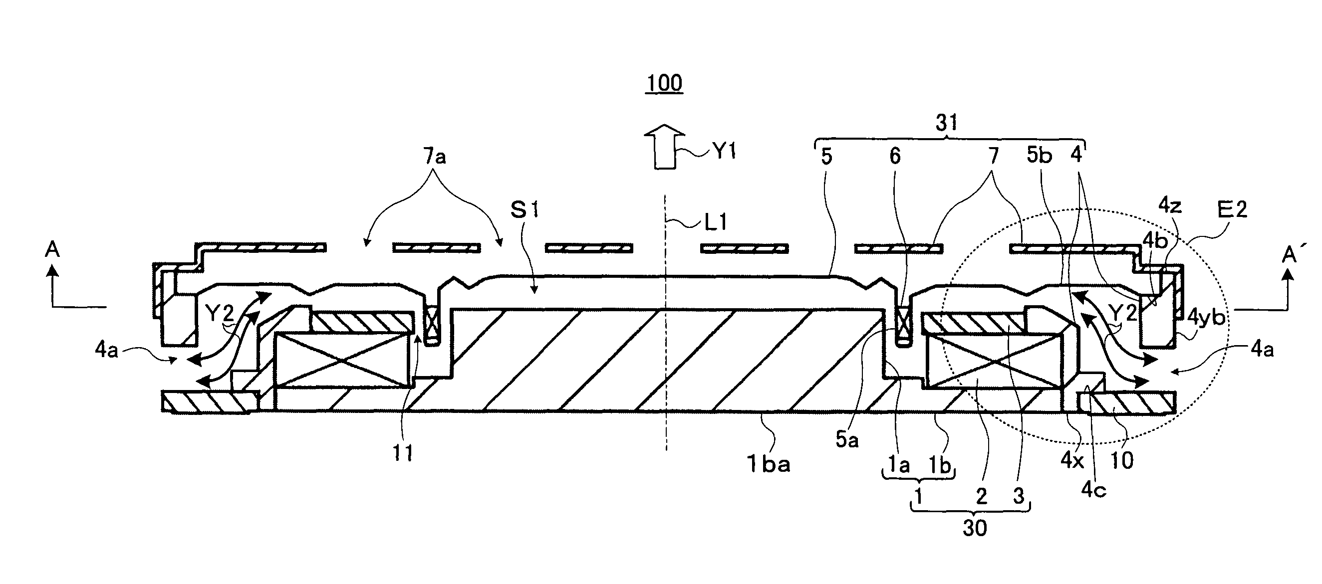
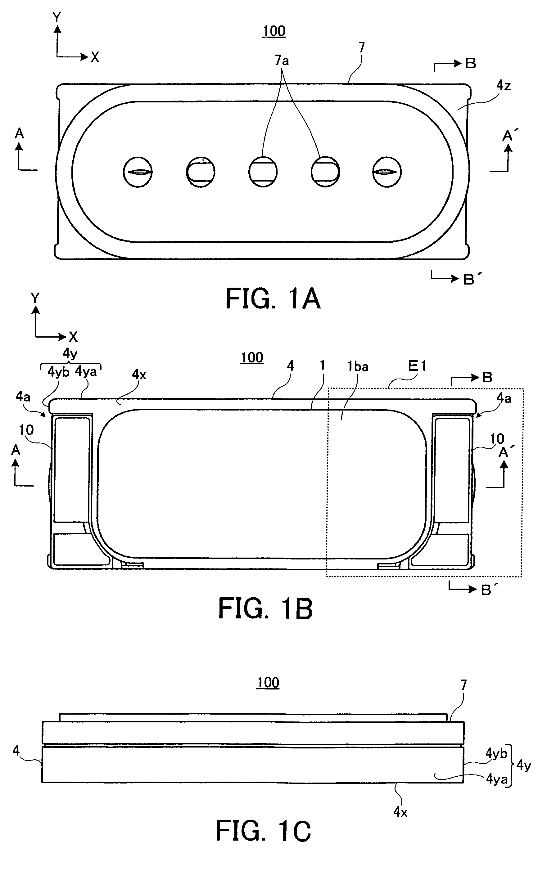
[0014]Particularly, the opening provided on the frame makes the one surface (e.g., the rear surface) and the additional surface (e.g., the side surface) communicate with each other, and the terminal is arranged at the position covering the opening of the one surface. Therefore, the opening on the one surface is covered, but the opening on the additional surface is open. Thus, ventilation performance of the speaker device is maintained. In addition, by such amount that the opening on the one surface is covered, the setting space of the terminal can be enlarged on the one surface.
[0024]In this manner, the speaker device further includes the voice coil and the diaphragm having a recessed part for holding the voice coil. The outer peripheral portion of the diaphragm is mounted on the one end side of the additional surface (e.g., the side surface) positioned on the side opposite to the one surface (e.g., the rear surface), and the space is formed between the diaphragm and the magnetic circuit. At the same time, the space communicates with the opening. Thereby, since the ventilation performance in the speaker device becomes high, the inside of the device is cooled down, and it can be prevented that the pressure therein unnecessarily becomes high. Thereby, the diaphragm can smoothly move, and it can be prevented that the sensitivity becomes low.

Problems solved by technology

In the speaker device of this kind, at the time of the operation thereof, the voice coil is heated, and a temperature of an area there around becomes high, which problematically causes sensitivity deterioration.

Method used


Image

  • Speaker device
  • Speaker device
  • Speaker device

Examples


first embodiment

[0040]In the first embodiment, an opening for making the side surface and the rear surface communicate with each other is provided on the frame. Then, the terminal is arranged at the position covering the opening on the rear surface. Thereby, ventilation performance in the speaker device is ensured, and the setting space of the terminal on the frame is enlarged.

(Configuration of Speaker Device)

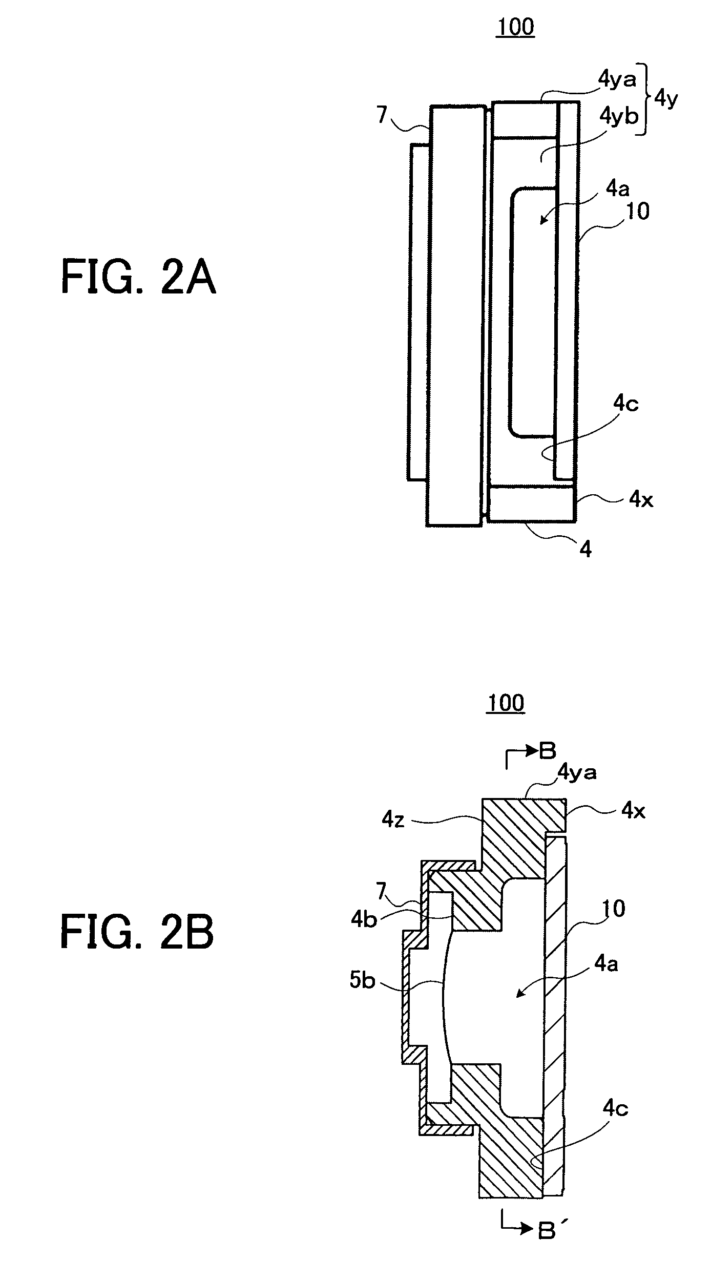
[0041]First, a description will be given of a configuration of a speaker device 100 according to a first embodiment of the present invention, with reference to FIG. 1A to FIG. 3.

[0042]FIG. 1A shows a front view of the speaker device 100. FIG. 1B shows a rear view of the speaker device 100. FIG. 1C shows a side view in a lateral direction of the speaker device 100 when the speaker device 100 shown in FIG. 1A is observed from a Y direction. FIG. 2A shows a side view in a longitudinal direction of the speaker device 100 when the speaker device 100 shown in FIG. 1A is observed in an X direction. F...

second embodiment

[0069]Next, a description will be given of the configuration of the speaker device according to a second embodiment of the present invention, with reference to FIGS. 8A and 8B to FIG. 10. Hereinafter, the same reference numerals are given to the same components as those of the first embodiment, and only points different from the first embodiment will be explained.

[0070]FIG. 8A is a view showing the rear surface of a speaker device 200 according to the second embodiment, corresponding to FIG. 1B. FIG. 8B is a side view of the speaker device 200 shown in FIG. 8A when observed from the Y direction. FIG. 9 is a cross-sectional view of the speaker device 200 taken along a cutting-line E-E′ shown in FIG. 8A. FIG. 10 is a cross-sectional view of the speaker device 200 taken along a cutting-line F-F′ in FIG. 8A.

[0071]In the first embodiment, the ventilation opening 4a provided on the frame 4 is formed to make the rear surface 4x of the frame 4 and the side surface 4yb positioned in the long...

third embodiment

[0074]Next, a description will be given of a configuration of a speaker device 300 according to a third embodiment of the present invention, with reference to FIGS. 11A and 11B to FIG. 13. Hereinafter, the same reference numerals are given to the same components as those of the first embodiment, and only points different from the first embodiment will be simply explained.

[0075]FIG. 11A is a rear view of the speaker device 300 according to the third embodiment, corresponding to FIG. 1B. FIG. 11B is across-sectional view taken along a cutting line G-G′ of the speaker device 300 shown in FIG. 11A. FIG. 12A is a side view of the speaker device 300 shown in FIG. 11A when observed from the X direction. FIG. 12B is a cross-sectional view of the speaker device 300 taken along a cutting-line H-H′ shown in FIG. 11A. FIG. 13 is a partly-enlarged cross-sectional view corresponding to a broken-line area E8 shown in FIG. 12A.

[0076]In the first embodiment, the ventilation opening 4a provided on th...


PUM


Abstract

A speaker device includes a magnetic circuit, a vibration system, a frame and a terminal. The frame is formed into a frame shape, and an inner wall thereof holds the magnetic circuit. Particularly, the frame has an opening for ventilation, which makes a rear surface positioned on a side opposite to a sound output direction and a side surface curved to a direction of the sound output direction from a peripheral end of the rear surface communicate with each other, and the terminal covers the opening on the rear surface of the frame. Therefore, the opening is provided on the side surface of the frame, and ventilation performance of the speaker device is ensured. In addition, by such amount that no opening is provided on the rear surface of the frame, a setting space of the terminal can be enlarged on the rear surface of the frame.

Description

BACKGROUND OF THE INVENTION[0001]1. Field of the Invention[0002]The present invention relates to a mounting configuration of a frame and a terminal for a speaker device.[0003]2. Description of Related Art[0004]Recently, a speaker device is used for various kinds of information equipments such as a mobile phone, PDA (Personal Digital Assistants) and a laptop personal computer.[0005]The speaker device includes a magnetic circuit having a yoke, a magnet and a plate, a vibration system having a voice coil and a diaphragm, and a frame. In addition, the speaker device has a terminal connected to a lead wire of the voice coil and an external circuit at appropriate positions on the frame. Therefore, in the speaker device, at the time of operation thereof, an audio signal and power are supplied to the voice coil via the terminal and the lead wire of the voice coil from the external circuit, and an acoustic wave is emitted by the diaphragm.[0006]As the speaker device of this kind, there is kn...

Claims


Application Information

Patent Timeline
Patent Type & Authority Patents(United States)
IPC IPC(8): H04R25/00
CPCH04R9/022H04R1/06H04R9/025
Inventor CHIBA, SATOSHIHIRAMUKI, SHUNICHI
Owner PIONEER CORP
Learn More