
Impact power tool

a power tool and rubber ring technology, applied in the field of impact power tools, can solve the problems of difficult to provide the hardness of the rubber ring, and achieve the effect of reducing the impact for

Active Publication Date: 2011-02-01
MAKITA CORP
View PDF17 Cites 5 Cited by
  • Summary
  • Abstract
  • Description
  • Claims
  • Application Information

AI Technical Summary

Benefits of technology

[0006]Accordingly, it is an object of the present invention to provide a technique that contributes to reduction of an impact force caused by rebound of a tool bit after its striking movement in an impact power tool.
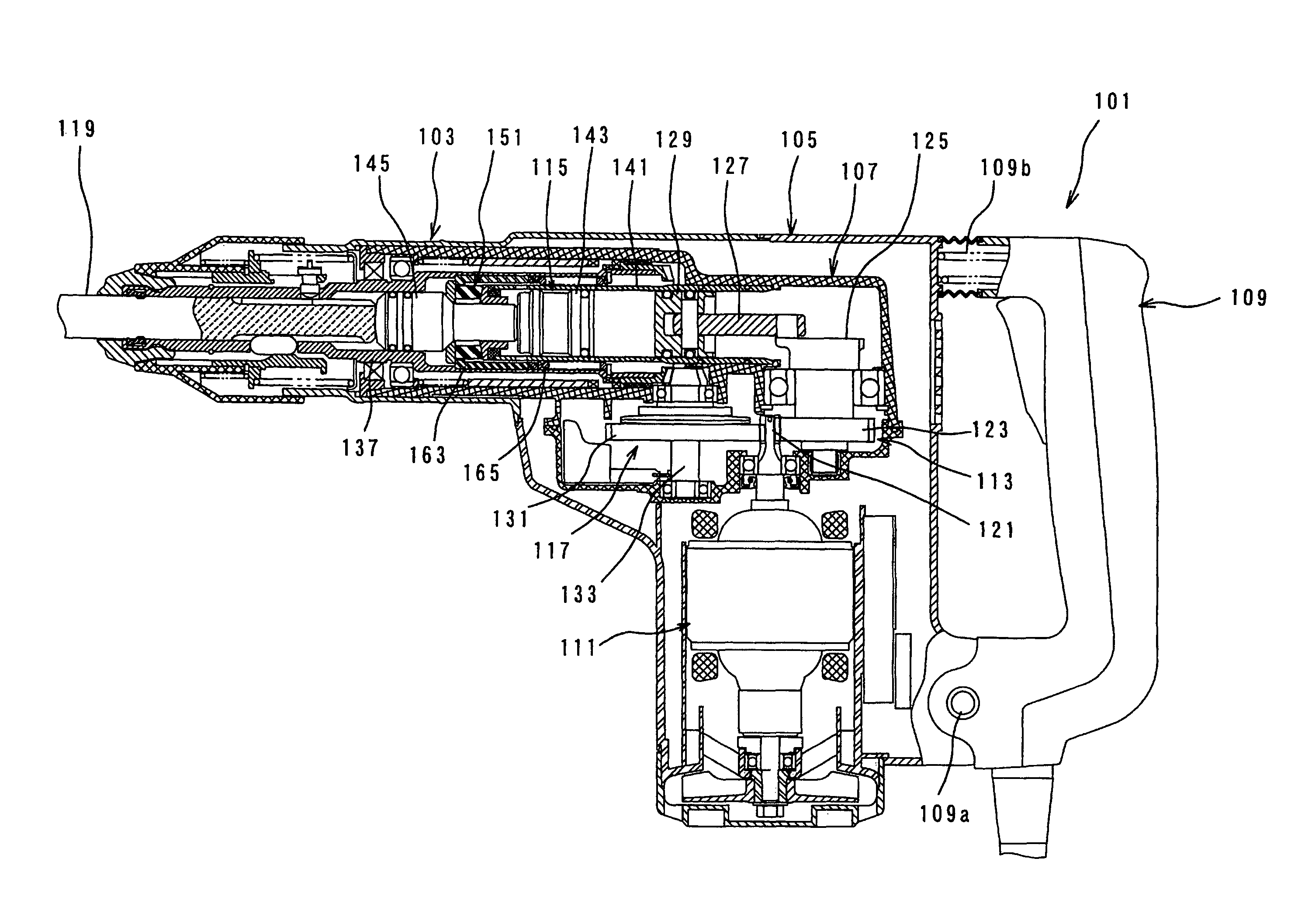
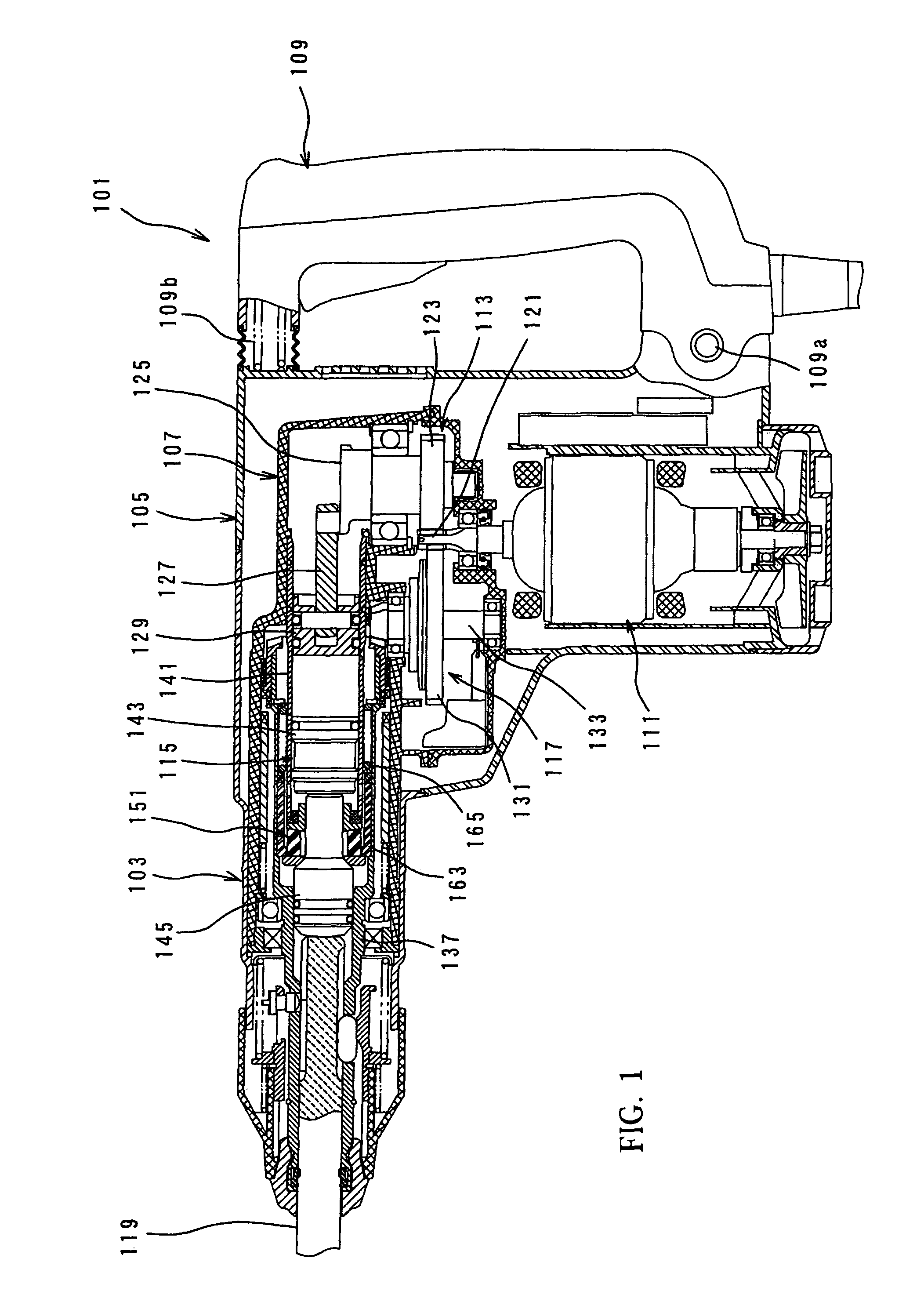
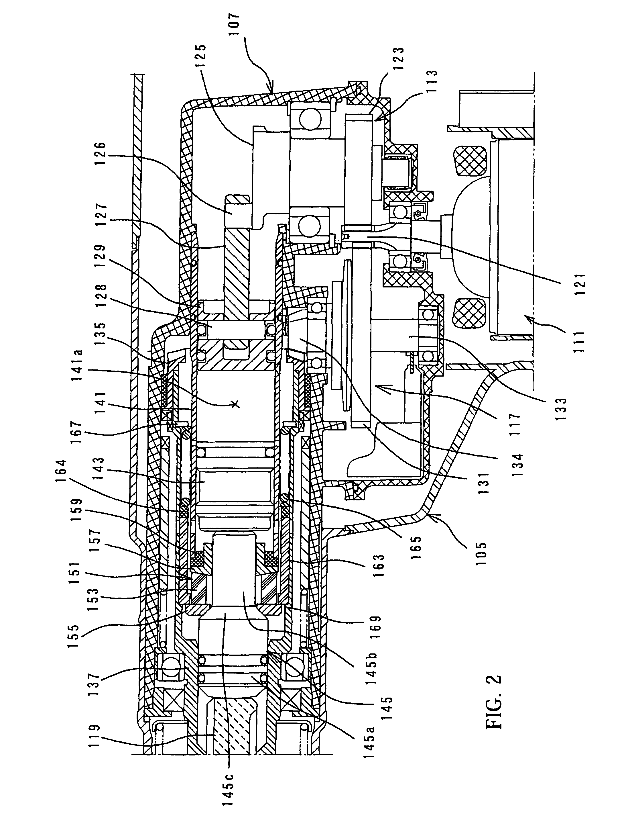
[0009]During hammering operation, the hammer actuating member is caused to rebound by receiving the reaction force of the workpiece after striking movement. According to this invention, with the construction in which the reaction force is transmitted from the hammer actuating member to the weight in the reaction force transmitting position in which the weight is placed in direct contact with the hammer actuating member or in which the weight is placed in contact with the hammer actuating member via an intervening member made of hard metal, the reaction force is nearly 100% transmitted. In other words, the reaction force is transmitted by exchange of momentum between the hammer actuating member and the weight. By this transmission of the reaction force, the weight is caused to move rearward in the direction of action of the reaction force. The rearward moving weight elastically deforms the elastic element, and the reaction force of the weight is absorbed by such elastic deformation. Specifically, according to this invention, the reaction force caused by rebound of the hammer actuating member can be absorbed by the rearward movement of the weight and by the elastic deformation of the elastic element which is caused by the movement of the weight. As a result, vibration of the impact power tool can be reduced.
[0011]According to the invention, the mass of the weight is set about 40% or more of the mass of the striker. As a result, the peak acceleration generated by the reaction force of rebound when the striking movement is performed can be advantageously reduced.
[0012]As one aspect of the invention, high vibration reducing function is performed when the mass of the weight is set in the range of the lower limit of about 40% of the mass of the striker to the upper limit of about 200% of the mass of the striker. Particularly, when the mass of the weight is about 80% of the mass of the striker, the vibration reducing effect can be further enhanced. Further, when the mass of the weight is about 200% of the mass of the striker, the vibration reducing effect can be practically maximized. Further, this vibration reducing effect can also be maintained with the weight having a further increased mass over 200%. However, the mass of the weight may preferably be set to about 200% or below of the mass of the striker due to the balance between the mass ratio of the weight and the entire mass of the hammer drill.
[0014]Having regard to this problem, according to one aspect of the invention, a resonance frequency defined under the assumption that the weight and the elastic element are models of a spring mass system may be set over half of the period of striking which is performed on the hammer actuating member by the striker. With such a construction, the weight can be returned to the initial reaction force transmitting position by the time the striker performs the next striking after the weight is caused to move rearward by receiving the reaction force from the hammer actuating member. Therefore, the weight and the elastic element can reliably function for each stroke of the striker. Thus, the vibration reducing performance can be increased.
[0017]During hammering operation, a reaction force caused by rebound of the hammer actuating member is transmitted to the weight and produces a stress wave in the weight. With such construction, the stress wave produced in the weight can be absorbed by deformation of the viscoelastic member. Therefore, when the elastic element comprises a spring, the spring can be prevented from surging which may be caused by transmission of the stress wave to the spring. Thus, the spring can be protected.

Problems solved by technology

It is difficult to provide the rubber ring with a hardness that satisfies the both functional requirements.

Method used


Image

  • Impact power tool
  • Impact power tool
  • Impact power tool

Examples


Embodiment Construction

[0028]Each of the additional features and method steps disclosed above and below may be utilized separately or in conjunction with other features and method steps to provide and manufacture improved impact power tools and method for using such impact power tools and devices utilized therein. Representative examples of the present invention, which examples utilized many of these additional features and method steps in conjunction, will now be described in detail with reference to the drawing. This detailed description is merely intended to teach a person skilled in the art further details for practicing preferred aspects of the present teachings and is not intended to limit the scope of the invention. Only the claims define the scope of the claimed invention. Therefore, combinations of features and steps disclosed within the following detailed description may not be necessary to practice the invention in the broadest sense, and are instead taught merely to particularly describe some ...


PUM

PropertyMeasurementUnit
massaaaaaaaaaa
massaaaaaaaaaa
massaaaaaaaaaa

Abstract

It is an object of the invention to provide a technique for a reduction of an impact force cased by rebound of a tool bit after its striking movement in an impact power tool. The representative impact power tool includes a tool body, a hammer actuating member, a striker, a weight and an elastic element. A reaction force is transmitted from the hammer actuating member to the weight and the elastic element is elastically deformed when the weight moves ward by the reaction to absorb the reaction force. The invention is characterized in that the mass of the weight is set to about 40% or more of the mass of the striker.

Description

BACKGROUND OF THE INVENTION[0001]1. Field of the Invention[0002]The present invention relates to an impact power tool for performing a linear hammering operation on a workpiece, and more particularly to a technique for cushioning a reaction force received from the workpiece during hammering operation.[0003]2. Description of the Related Art[0004]Japanese non-examined laid-open Patent Publication No. 8-318342 discloses a technique for cushioning an impact force caused by rebound of a tool bit after its striking movement in a hammer drill. In this known hammer drill, a rubber ring (cushion member) is disposed between the axial end surface of a cylinder on the body side and an intermediate element in the form of an impact bolt which strikes the tool bit When the tool bit receives a reaction force from the workpiece and rebounds after striking movement of the tool bit, the impact bolt collides with the rubber ring. At this time, the rubber ring cushions the impact force by elastic deform...

Claims


Application Information

Patent Timeline
Patent Type & Authority Patents(United States)
IPC IPC(8): B25D17/24
CPCB25D17/06B25D17/24B25D2211/003B25D2211/068B25D2250/371
Inventor AOKI, YONOSUKE
Owner MAKITA CORP
Learn More