
Actuator for optical pickup

a technology of optical pickup and actuator, which is applied in the field of electromagnetically controlled actuators, can solve the problems of unable to meet the demands of reactive speed and precision, and discrimination of certain media, and achieve the effect of fast and precise manner

Inactive Publication Date: 2011-01-18
TOPRAY MEMS
View PDF4 Cites 0 Cited by
  • Summary
  • Abstract
  • Description
  • Claims
  • Application Information

AI Technical Summary

Benefits of technology

[0006]The present invention has been made to overcome the above-mentioned drawback of a conventional actuator. The primary object of the present invention is to provide an actuator capable of providing movement forces in three directions so that the optical pickup can tune the reflected laser beam angle in a fast and precise manner.
[0007]To achieve the aforementioned object, the present invention provides an actuator capable of providing movement forces in a first direction, a second direction, and a third direction. The actuator includes two sets of repelling permanent magnets and yokes, a focusing coil, a tracking coil, and a tilting coil. The repelling and attractive fields generated by the permanent magnets enable the coils to generate independent movements in three axial directions.
[0012]The experiments of the actuator of the present invention show that the average force for movement is ⅓ more than the conventional design. The increase in the exerted force increases the movement speed. In addition, the actuator of the present invention provides movement forces in three independent directions. In comparison, the actuator of the present invention is fast and precise in tuning the optical pickup to guide the laser beam to alleviate the selective and discriminative problem in the playing / recording devices.

Problems solved by technology

Because the media quality of different manufactures and the stability of a loading tray may vary, a playing device may be very selective and critical to the media quality and result in the discrimination of certain media.
However, the conventional actuator fails to meet the demands of the reactive speed and the precision in the current application; therefore, it is important to develop an actuator to provide fast and precise movement forces to tune the lens.

Method used


Image

  • Actuator for optical pickup
  • Actuator for optical pickup
  • Actuator for optical pickup

Examples


Embodiment Construction

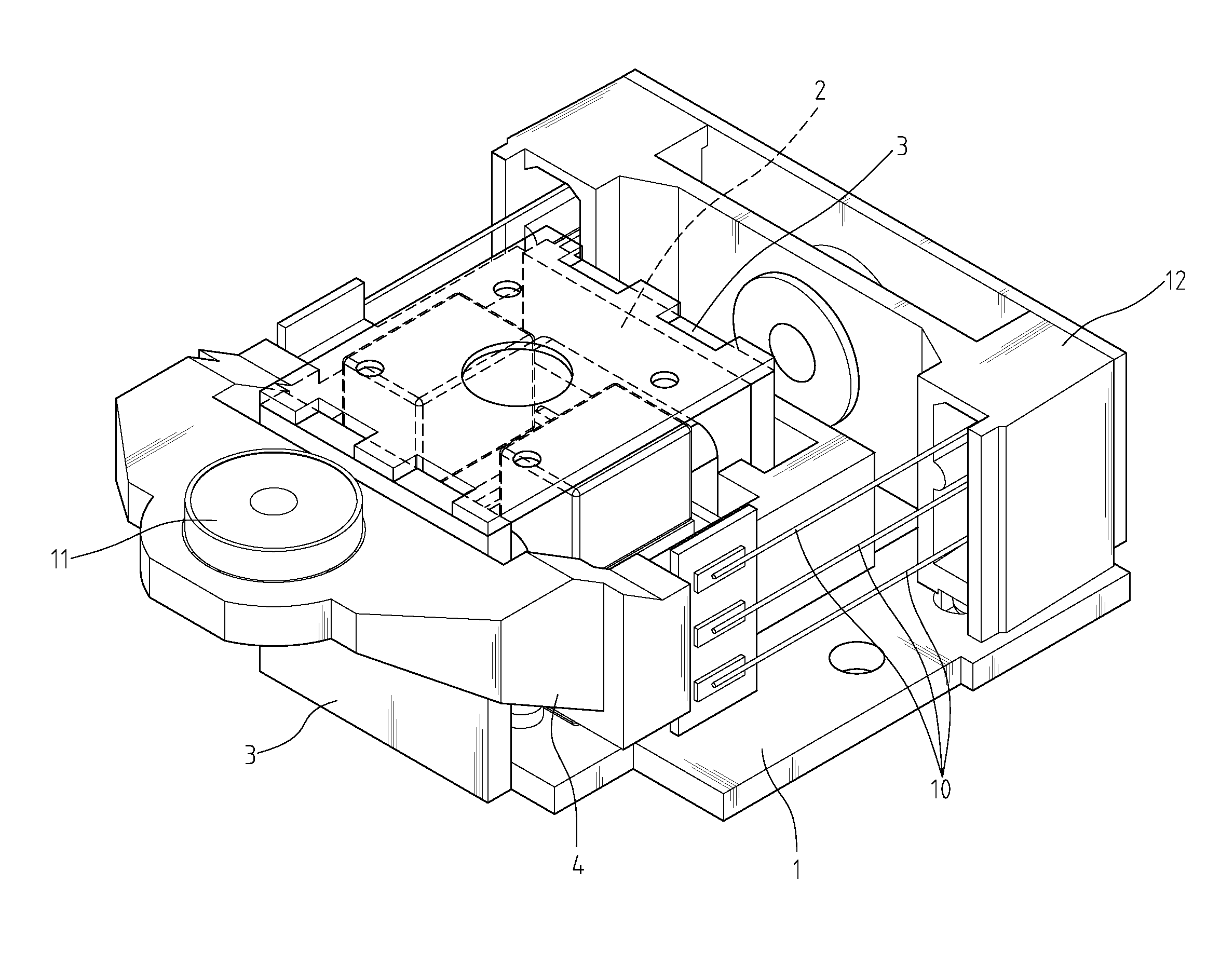
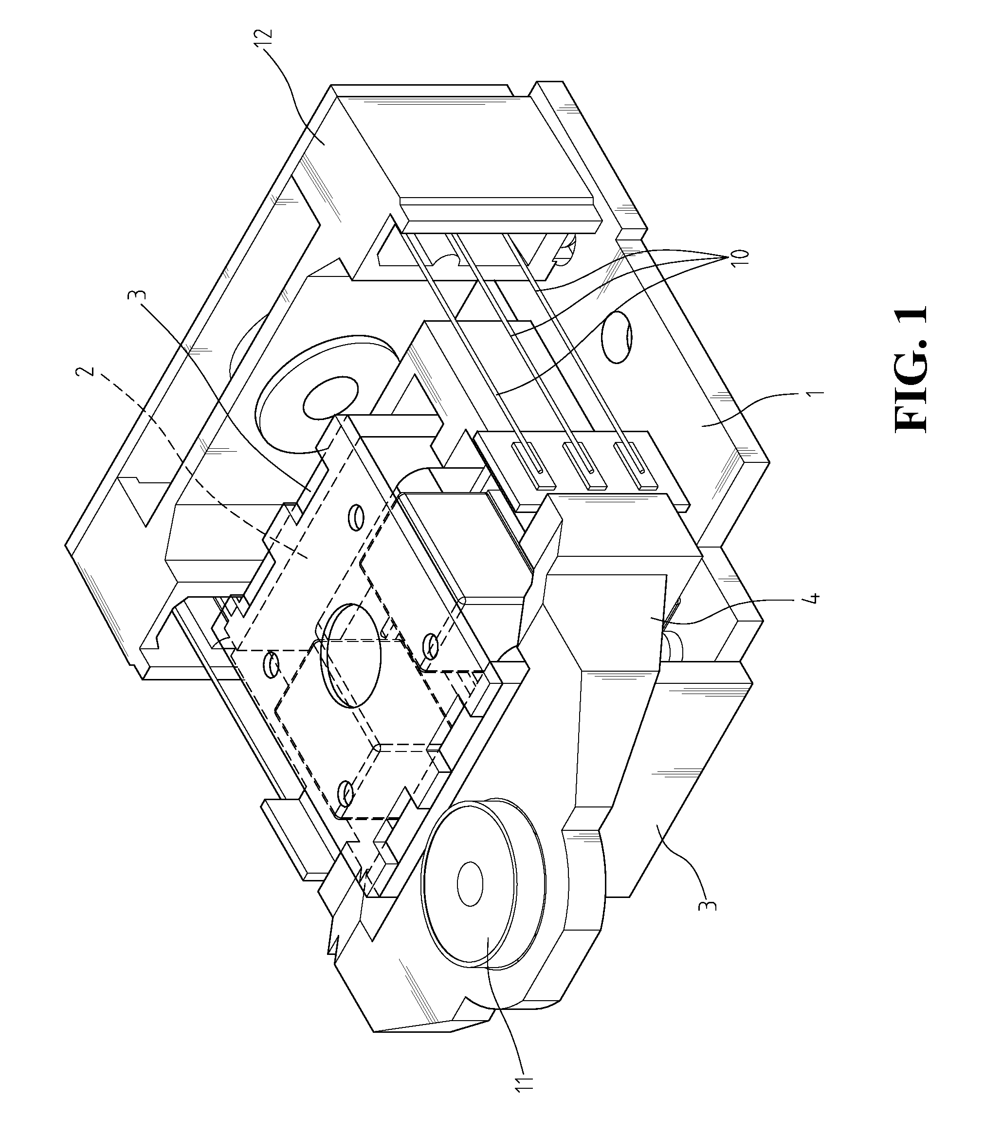
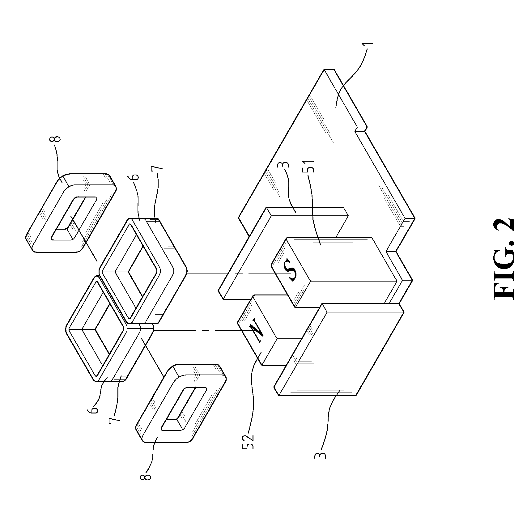
[0023]Refer to FIGS. 1-3. FIG. 1 shows the three-dimensional view of the present invention, FIG. 2 shows an exploded view of the elements of the present invention, and FIG. 3 shows a schematic view of the N-pole and S-pole of the magnets of the present invention. An actuator of the present invention includes a bottom yoke 1, a top yoke 2, a yoke pair 3, a lens holder 4, two pairs of permanent magnets 51, 52, a focusing coil 6, a tilting coil 7, a tracking coil 8, a steel wire set 10, a lens 11, and a base 12.

[0024]Bottom yoke 1 is connected to yoke pair 3 and base 12. The top of yoke pair 3 is connected to top yoke 2. Both sides of base 12 are connected to steel wire set 10, which is connected to lens holder 4 so that lens holder 4 is a hanging moveable object. Lens holder 4 holds lens 11.

[0025]Permanent magnet set 51 includes magnet 511, 512, and a yoke 513. Permanent magnet set 52 includes magnet 521, 522, and a yoke 523. Permanent magnet sets 51, 52 are next to each other with a ...


PUM

PropertyMeasurementUnit
magnetic fieldsaaaaaaaaaa
sizeaaaaaaaaaa
optical diffractive propertyaaaaaaaaaa

Abstract

An actuator capable of providing movement forces in a first direction, a second direction, and a third direction is provided. The actuator includes two sets of repelling permanent magnets and yokes, a focusing coil, a tracking coil, and a tilting coil. The repelling and attractive fields generated by the permanent magnets enable the coils to generate independent movements in three axial directions. The two sets of permanent magnets are placed in a repelling position, with a small space between the two magnets to generate a field whose magnetic forces repel and attract within the surrounding range. The focusing, tilting and tracking coils are engaged with the lens holder whose movements in the first, second and third directions are determined by the amplitude and direction of the electric current in the focusing, tilting and tracking coils respectively.

Description

FIELD OF THE INVENTION[0001]The present invention generally relates to an electromagnetic actuator, and more specifically to an electromagnetic actuator for optical pickup.BACKGROUND OF THE INVENTION[0002]Conventional optical storage media, such as CD, DVD, require a lens to focus the light source on a recording layer of the storage media to read and write data. The size of the recording spot is restricted by the optical diffractive property. To improve the recording density of the optical storage media, it is necessary to address the optical diffractive issues.[0003]The optical pickup is the most important component in the optical storage device. The operation of an optical pickup includes projecting a laser beam to the surface of the media, and using an object lens to guide the reflected laser beam to an optical sensor for reading and writing. Because the media quality of different manufactures and the stability of a loading tray may vary, a playing device may be very selective an...

Claims


Application Information

Patent Timeline
Patent Type & Authority Patents(United States)
IPC IPC(8): G11B7/00
CPCG11B7/0956G11B7/093G11B7/0933G11B7/0935
Inventor LIU, CHIN-SUNGTSAI, CHANG-MING
Owner TOPRAY MEMS
Learn More