
Solid state lighting apparatus

a lighting apparatus and solid state technology, applied in the field of solid state lighting, can solve the problems of inconvenient operation, inconvenient maintenance, and inconvenient maintenance, and achieve the effect of reducing maintenance costs, reducing maintenance costs, and reducing maintenance costs

Active Publication Date: 2010-12-28
ELEMEDIA TECH OF AMERICA LLC
View PDF6 Cites 74 Cited by
  • Summary
  • Abstract
  • Description
  • Claims
  • Application Information

AI Technical Summary

Benefits of technology

"The present invention provides a solid state lighting apparatus and assembly that includes a current limiting device for controlling the current delivered to a solid state lamp. The current limiting device functions as a constant current source, and a power converter converts AC power to DC power for the current limiting device. The lighting apparatus operates at less than 100% duty cycle from an AC line frequency. The apparatus includes a housing for attachment to existing power lines, and a circuit board for electrical connection. The technical effects include improved control of current, reduced power consumption, and improved efficiency of solid state lighting."

Problems solved by technology

Incandescent bulbs are inexpensive to buy, but generate 90% heat and merely 10% of light, which makes them inefficient and expensive to operate.
Further, incandescent bulbs have a very short product life (typically 1000 hours).
In addition, fluorescent lamps require bulky ballasts that are costly, and make the fluorescent lamps unsuitable for smaller spaces.
Further, fluorescent lamps perform poorly in low temperatures.
Though fluorescent lamps exhibit longer life than incandescent bulbs, fluorescent lamps are more expensive than incandescent bulbs and still require frequent maintenance, which is fulfilled by intensive labor.

Method used


Image

  • Solid state lighting apparatus
  • Solid state lighting apparatus
  • Solid state lighting apparatus

Examples


Embodiment Construction

[0020]The present invention provides a lighting apparatus using solid state lighting elements, for such application as replacing incandescent bulbs and fluorescent lamps, while providing more efficient, longer life lighting (50,000 hours typical) that is also environmentally friendly and compact.

[0021]The lighting apparatus further allows for more compact fabrication than in conventional incandescent and fluorescent lighting. The lighting apparatus can further be fabricated to fit into existing incandescent or fluorescent bulb form factors, which in turn allows the lighting apparatus to be easily fit into existing housing and wiring for incandescent or fluorescent lighting.

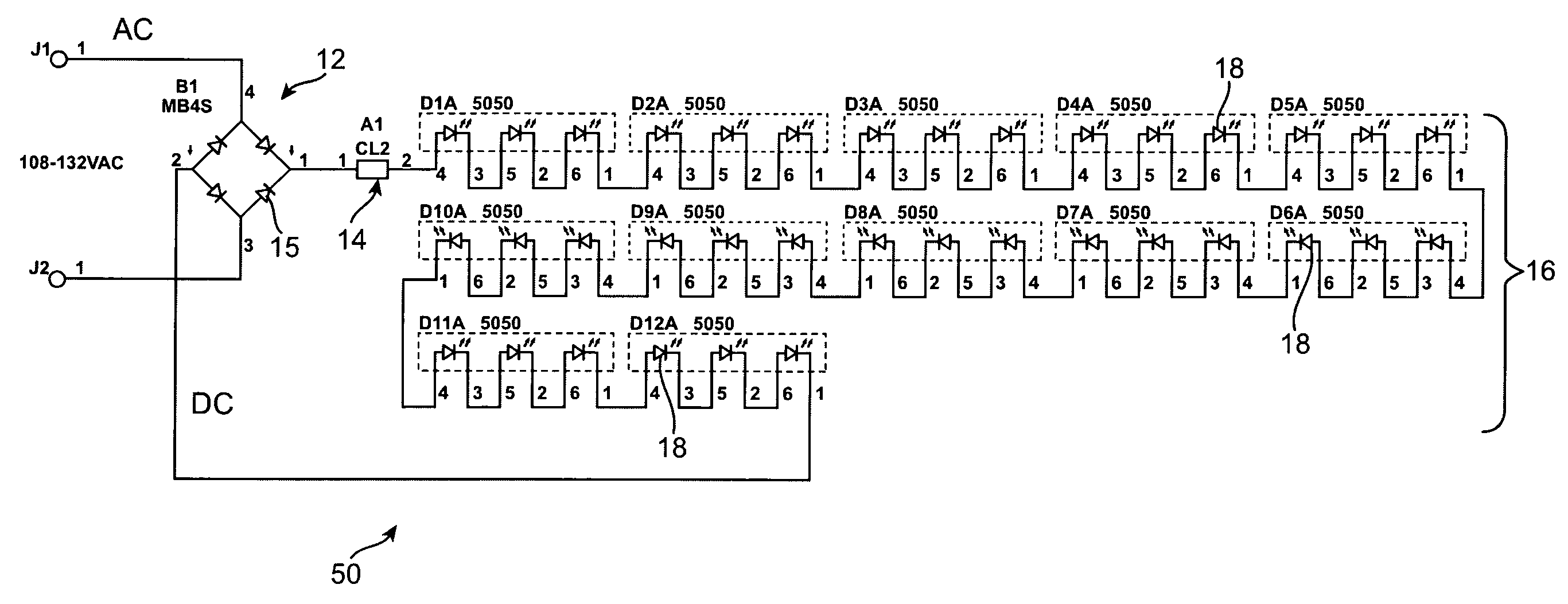
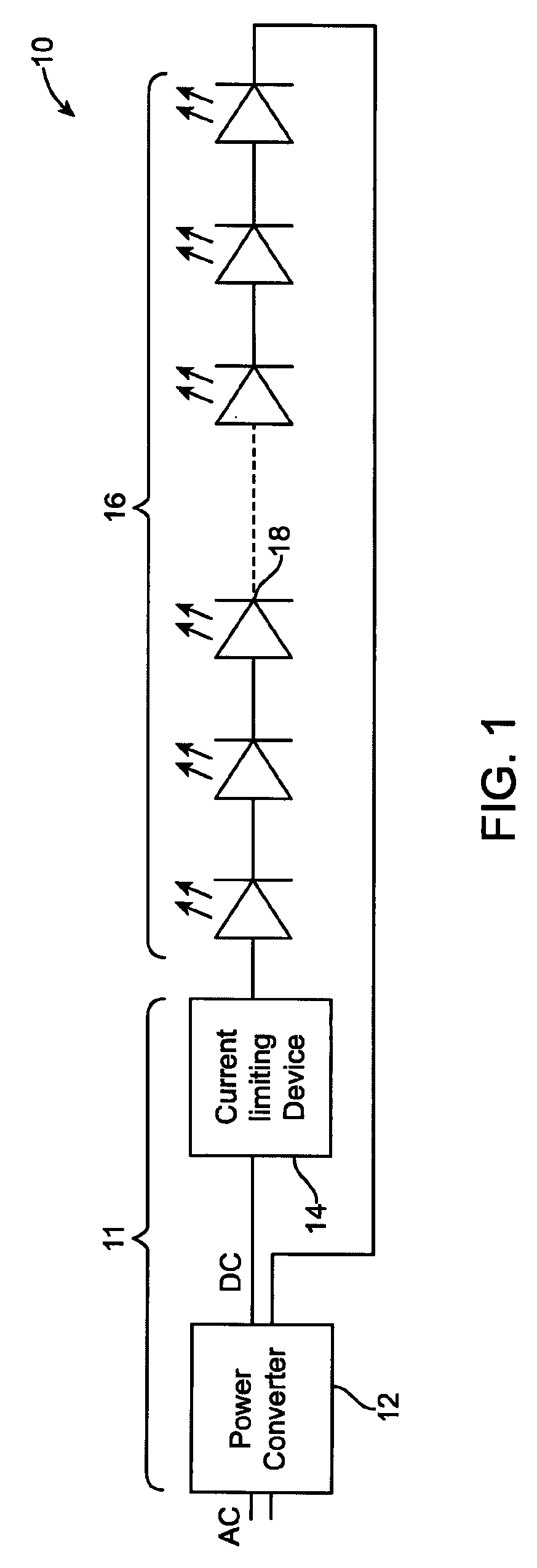
[0022]FIG. 1 shows an example functional block diagram of a lighting apparatus 10, according to an embodiment of the present invention. The lighting apparatus 10 comprises a power circuit 11 including a power converter 12, such as bridge a rectifier, that converts alternating current (AC) to direct current (DC).

[0...


PUM


Abstract

A lighting apparatus includes a solid state lamp including one or more solid state lighting elements, and a power circuit including a current limiting device electrically connected to the lamp. The current limiting device configured to impose a maximum threshold on the current delivered to the lamp, wherein the current limiting device functions as essentially a constant current source. The lighting apparatus includes a housing for the power circuit and lamp, as a module unit.

Description

RELATED APPLICATION[0001]This application claims priority from U.S. Provisional Patent Application Ser. No. 60 / 926,140 filed Apr. 25, 2007 incorporated herein by reference in its entirety. This application further claims priority from U.S. Provisional Patent Application Ser. No. 60 / 926,476 filed Apr. 27, 2007, incorporated herein by reference in its entirety.FIELD OF THE INVENTION[0002]The present invention relates to lighting applications, and in particular to solid state lighting.BACKGROUND OF THE INVENTION[0003]There has been an ongoing global proliferation of lighting products. Typical lighting products use one or more incandescent bulbs. Incandescent bulbs are inexpensive to buy, but generate 90% heat and merely 10% of light, which makes them inefficient and expensive to operate. Further, incandescent bulbs have a very short product life (typically 1000 hours).[0004]Fluorescent lamps are more efficient than incandescent bulbs, but utilize hazardous materials such as mercury. In...

Claims


Application Information

Patent Timeline
Patent Type & Authority Patents(United States)
IPC IPC(8): H05B41/36
CPCH05B33/0803H05B33/0809Y02B20/383F21S8/00F21V23/005F21Y2103/10F21Y2115/10Y02B20/30H05B45/3574H05B45/3578
Inventor LEE, GEORGEYOUNG, ARTHUR
Owner ELEMEDIA TECH OF AMERICA LLC
Learn More