Electrical connecting apparatus

a technology of electrical connection and connecting device, which is applied in the direction of electrical testing, measurement devices, instruments, etc., can solve the problems of difficulty in adjusting to have such multiple probes adequately contact respective corresponding pads on the semiconductor wafer, complex and needs skill, and inability to adjust to have such multiple probes in the same direction, etc., to achieve stable insertion, improve durability, and reduce vibration. effect of looseness

Active Publication Date: 2010-11-30
NIHON MICRONICS
View PDF11 Cites 8 Cited by
  • Summary
  • Abstract
  • Description
  • Claims
  • Application Information

AI Technical Summary

Benefits of technology

[0026]According to the electrical connecting apparatus of the present invention, the spacer for holding the probe board on the support member can be stably disposed, so that the looseness due to vibration can be prevented, and the probe board can be surely supported on the support member, thereby improving the durability.

Problems solved by technology

The operation to adjust so that all the probe tips are adequately contact each of corresponding electrical connection terminals of the device under test is complicated and needs skill.
Particularly, in an investigation of multiple integrated circuits formed on a semiconductor wafer, the number of probes of the probe assembly is remarkably increased, so that an operation to adjust to have such multiple probes adequately contact respective corresponding pads on the semiconductor wafer is not easy.
In a spacer of this type, however, if both end faces are flat planes orthogonal to the axis of the spacer and an inclination is caused on the reference plane of the support member due to deflection or distortion of, e.g., the support member receiving the end faces, an end face of the spacer and the contact face of the support member for receiving the end face do not abut uniformly in the peripheral direction of the spacer, so that the contacting relation between both becomes unstable.
Also, if an inclination is caused by a production error in a through hole, which permits the spacer to penetrate therethrough, formed on the wiring board to be inserted between the probe board and the support member, the contact relationship between the support member receiving the end face and the contact face of the support member which receives the end face or the contact face of the probe board becomes likewise unstable.
If the contact relationship between the end face of the spacer and the support member receiving the end face or the contact face of the probe board is unstable, slackness in tightening of the bolt supporting the probe board on the support member might be caused due to a lingered strong vibration, resulting in degradation in durability.

Method used


Image

  • Electrical connecting apparatus
  • Electrical connecting apparatus
  • Electrical connecting apparatus

Examples


Embodiment Construction

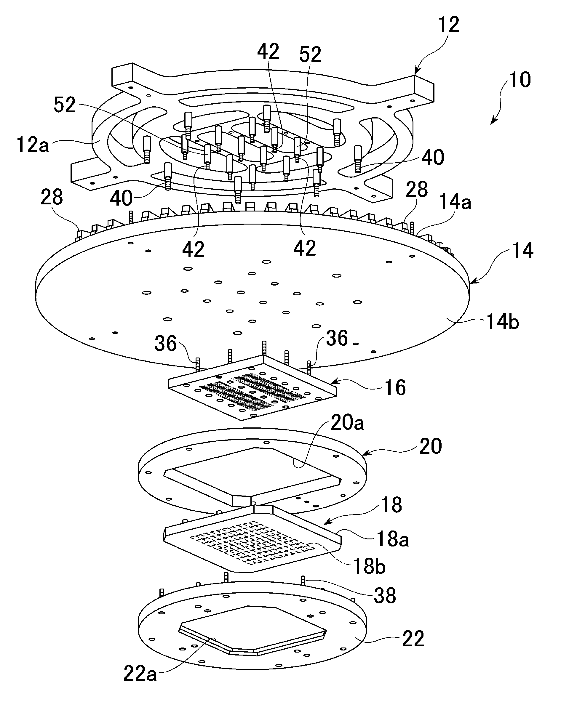
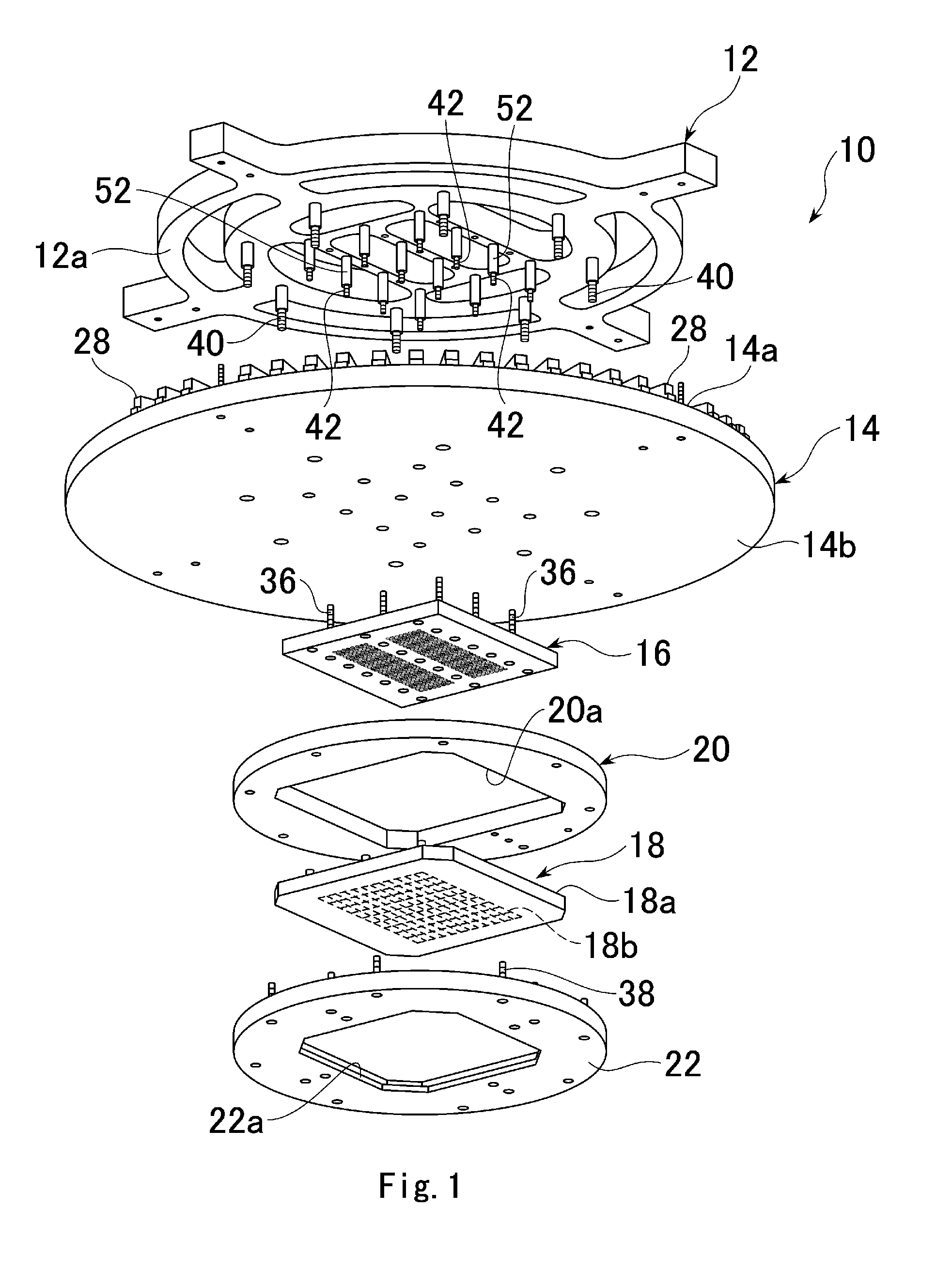
[0051]The electrical connecting apparatus 10 according to the present invention is shown in FIG. 1 in an exploded state. This electrical connecting apparatus 10 comprises: a flat plate-like support member 12 whose underside 12a is a flat mounting reference plane; a circular flat plate-like wiring board 14 to be held on the mounting surface 12a of the support member; a probe assembly 18 to be electrically connected to the wiring board 14 via an electric connector 16; a base ring 20 with a central opening 20a for receiving the electric connector 16 formed; and a fixed ring 22 for sandwiching the edge portion of the probe assembly 18 together with the edge portion of the central opening 20a of the base ring. This fixed ring 22 has in its central portion a central opening 22a for permitting exposure of probes 18b mentioned later of the probe assembly 18.

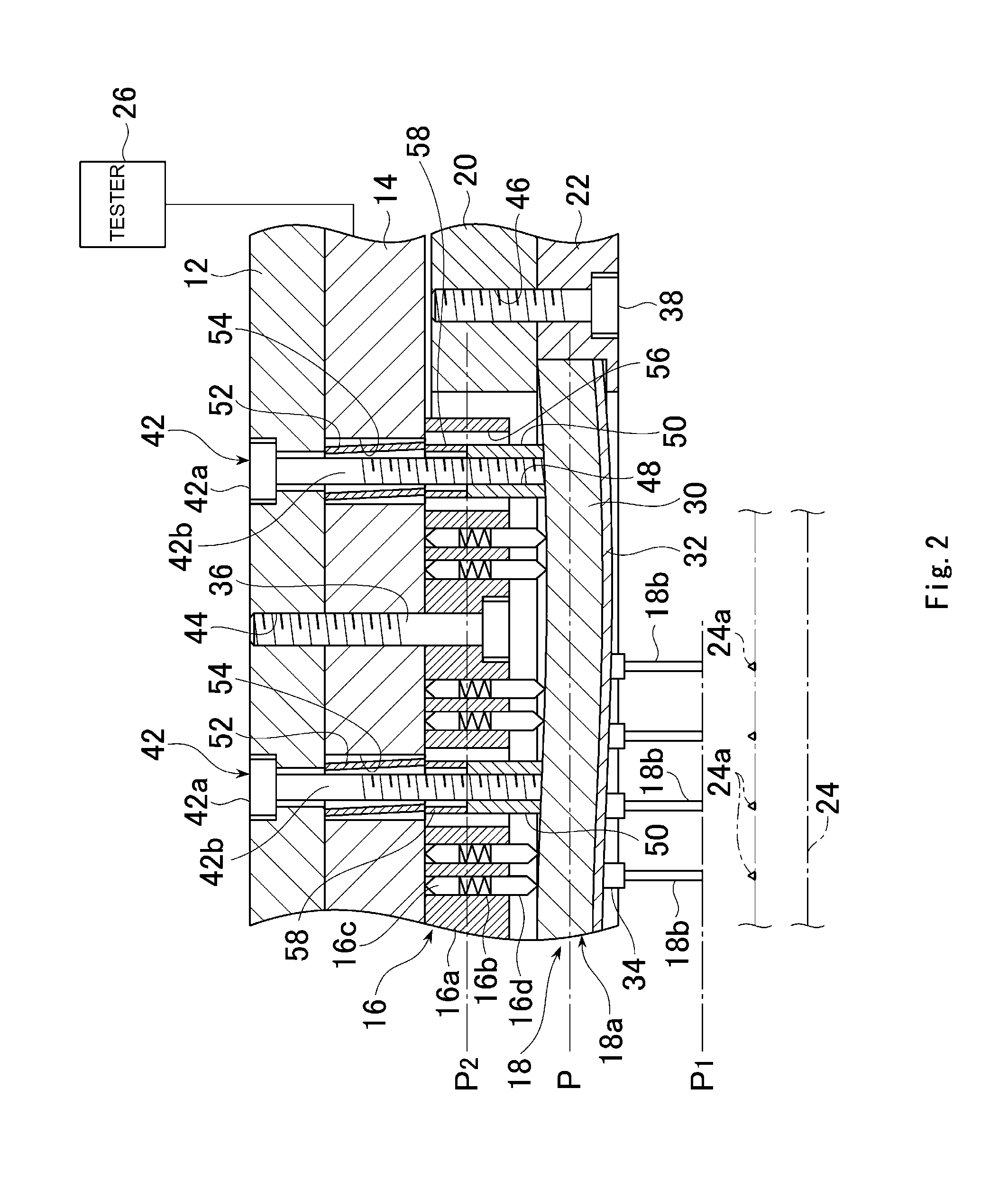
[0052]These members 12-22 are, as shown in FIG. 2, integrally assembled and used for connecting each connection pad 24a which is a conn...


PUM


Abstract

An electrical connecting apparatus for use in an electrical inspection of a tester and a device under test. The electrical connecting apparatus is provided with a probe assembly to be tightened by tightening screw members toward the support member and having a wiring board interposed between itself and a support member. In order to prevent deformation of the probe board of the probe assembly due to tightening of the screw members, a spacer disposed to penetrate the wiring board is between the support member and probe board and penetrated by the screw members. Both end faces of the spacer are convex spherical surface.

Description

TECHNICAL FIELD[0001]The present invention relates to an electrical connecting apparatus such as a probe card for use in connection between a device under test such as an electric circuit of an integrated circuit and an electric circuit of a tester for conducting an electrical test of the device under test.BACKGROUND[0002]As one of electrical connecting apparatus of this type, there is provided an electrical connecting apparatus comprising a probe board and a plurality of probes extended from the probe board and capable of adjusting the flatness of the probe board (see Patent Document 1). According to this conventional electrical connecting apparatus, it is possible to apply pressing force or tensile force from a support member supporting the probe board to a part of the probe board. By adjusting this action force, even if bending is caused in the probe board of a probe assembly, the flatness of the probe board can be maintained by correcting the curved deformation of the probe boar...

Claims


Application Information

Patent Timeline
Patent Type & Authority Patents(United States)
IPC IPC(8): G01R31/04G01R31/02
CPCG01R31/2889
Inventor SATO, HITOSHIMIURA, KIYOTOSHI
Owner NIHON MICRONICS
Why Eureka
Try Eureka