Device for separating and concentrating microfluidic particles

a technology of microfluidic particles and injecting devices, which is applied in the direction of separation processes, laboratory glassware, instruments, etc., can solve the problems of inability to implement such methods and apparatus in a miniaturized or micro-sized and automated system, requiring a relatively long separation time, and a relatively complex injecting device. , to achieve the effect of high throughput, cost-effectiveness and small siz

Active Publication Date: 2010-11-23
WAYNE STATE UNIV
View PDF14 Cites 22 Cited by
  • Summary
  • Abstract
  • Description
  • Claims
  • Application Information

AI Technical Summary

Benefits of technology

[0006]The present invention generally provides microfluidic devices and methods for particle concentration and separation. Embodiments of the present invention provide continuous processing ability independent of a requirement of external fields. The devices and methods of the present invention are able to separate and concentrate particles by particle size and density. For example, the present invention provides a microfluidic separator that employs a momentum-driven particle separation principle. The separator provides a relatively high throughput with continuous-flow processing without a need of external fields for separation. The separator is configured to be stacked with arrays of other separators for large-volume cell separation. The separator has a relatively small size that is suitable as a portable device and for micro-scale analysis. Moreover, the separator is relatively cost effective and easy to be fabricated.
[0007]In one embodiment, the present invention provides a flow unit for microfluidic particle separation and concentration. The unit comprises a nozzle segment defined by a first member and a second member. The nozzle segment has an opening through which fluid and microfluidic particles enter the flow unit. The nozzle segment has a narrowing portion at which the first and second members narrow from the opening to increase momentum of the fluid through the nozzle segment. The unit further comprises a turn segment defined by the first member formed to flare outwardly downstream from the narrowing portion to change flow direction of the fluid consistent with the first member. The unit further comprises a diffuser segment defined by the second member extending past the turn segment to facilitate separation of the microfluidic particles from the fluid due to the inability to follow the fluid flow.
[0009]In another example, the present invention provides a method of separating and concentrating microfluidic particles. The method comprises receiving a fluid and microfluidic particles to be separated and concentrated, and accelerating the speed of the fluid and microfluidic particles to increase the momentum thereof. The method further includes influencing a change in direction of the fluid, and facilitating separation of the microfluidic particles from the fluid due to the inability to follow the fluid flow.

Problems solved by technology

Many of such methods and apparatus are not practical for implementation in a miniaturized or microsized and automated system.
Although other techniques may not require outer fields mentioned above, many of these techniques are not continuous and require a relatively long separation time and relatively complex injecting devices.
Although both CHDF and HDC do not require external fields, these separation processes are (as mentioned) not continuous and require a relatively long separation time and complicated injecting devices.
These attributes are not suitable for large-scale cell or particle preparation.

Method used


Image

  • Device for separating and concentrating microfluidic particles
  • Device for separating and concentrating microfluidic particles
  • Device for separating and concentrating microfluidic particles

Examples


Embodiment Construction

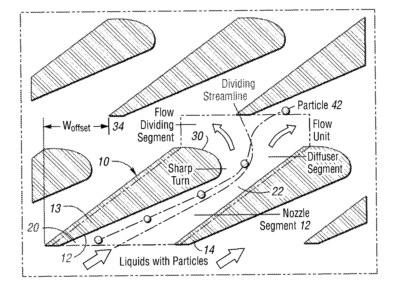
[0021]The present invention generally provides microfluidic devices and methods for particle concentration and separation. Embodiments of the present invention provide microfluidic devices having a continuous processing ability independent of a requirement for the use of external fields. The devices and methods of the present invention are able to separate and concentrate particles by particle size and density. For example, the present invention provides a microfluidic separating and concentrating device comprising a nozzle segment through which fluid and microfluidic particles enter and gain momentum, a turn segment that changes flow direction of the fluid, and a diffuser segment that facilitates separation of the microfluidic particles from the fluid.

[0022]FIGS. 1a and 1b illustrate a flow unit 10 for microfluidic particle separation and concentration in accordance with one embodiment of the present invention. As shown, the flow unit 10 comprises a nozzle segment 12 defined by a f...


PUM

PropertyMeasurementUnit
densitiesaaaaaaaaaa
densitiesaaaaaaaaaa
particle sizesaaaaaaaaaa

Abstract

A flow unit for microfluidic particles separation and concentration is disclosed. The unit comprises a nozzle segment, a turn segment, and a diffuser segment. The nozzle segment is defined by a first member and a second member, and has an opening through which fluid and microfluidic particles enter. The nozzle segment has a narrowing portion at which the first and second members narrow from the opening to increase momentum of the fluid therethrough. The turn segment is defined by the first member flaring outwardly downstream from the narrowing portion to change flow direction of the fluid consistent with the first member. The diffuser segment is defined by the second member extending past the turn segment to facilitate separation of the microfluidic particles from the fluid due to the inability to follow the fluid flow.

Description

CROSS-REFERENCE TO RELATED APPLICATIONS[0001]This application is a continuation of International Application No. PCT / US2007 / 011060, filed on May 7, 2007, entitled “DEVICE AND METHOD OF SEPARATING AND CONCENTRATING MICROFLUIDIC PARTICLES” and claims the benefit of U.S. Provisional Application Ser. No. 60 / 797,998, filed on May 5, 2006, entitled “DEVICE AND METHOD OF SEPARATING AND CONCENTRATING MICROFLUIDIC PARTICLES,” the entire contents of which are incorporated herein by reference.BACKGROUND OF THE INVENTION[0002]The present invention relates to flow separating and concentrating devices and, more particularly, flow units and methods of separating and concentrating microfluidic particles.[0003]Separation of cells, bacteria, or other particles is a process typically performed in biological, medical, and chemical research. Many technologies have been developed to replace conventional gradient methods that require bulky centrifuges and separation tubes. Many of such methods and apparat...

Claims


Application Information

Patent Timeline
Patent Type & Authority Patents(United States)
IPC IPC(8): B01L99/00
CPCG01N1/2202G01N1/40G01N15/0255
Inventor AUNER, GREGORY W.CHEN, CHUNG CHU
Owner WAYNE STATE UNIV
Why Eureka
Try Eureka