Centrifugal electric impact wrench
a centrifugal electric and wrench technology, applied in the field of centrifugal electric impact wrenches, can solve the problems of high coupling force of coupling members, difficulty in coupling bolts for old or disabled people, and difficulty in coupling bolts for coupling wheels to vehicles, etc., to achieve stably transmit power with high torque, reduce rotation force, and facilitate carrying
- Summary
- Abstract
- Description
- Claims
- Application Information
AI Technical Summary
Benefits of technology
Problems solved by technology
Method used
Image
Examples
first embodiment
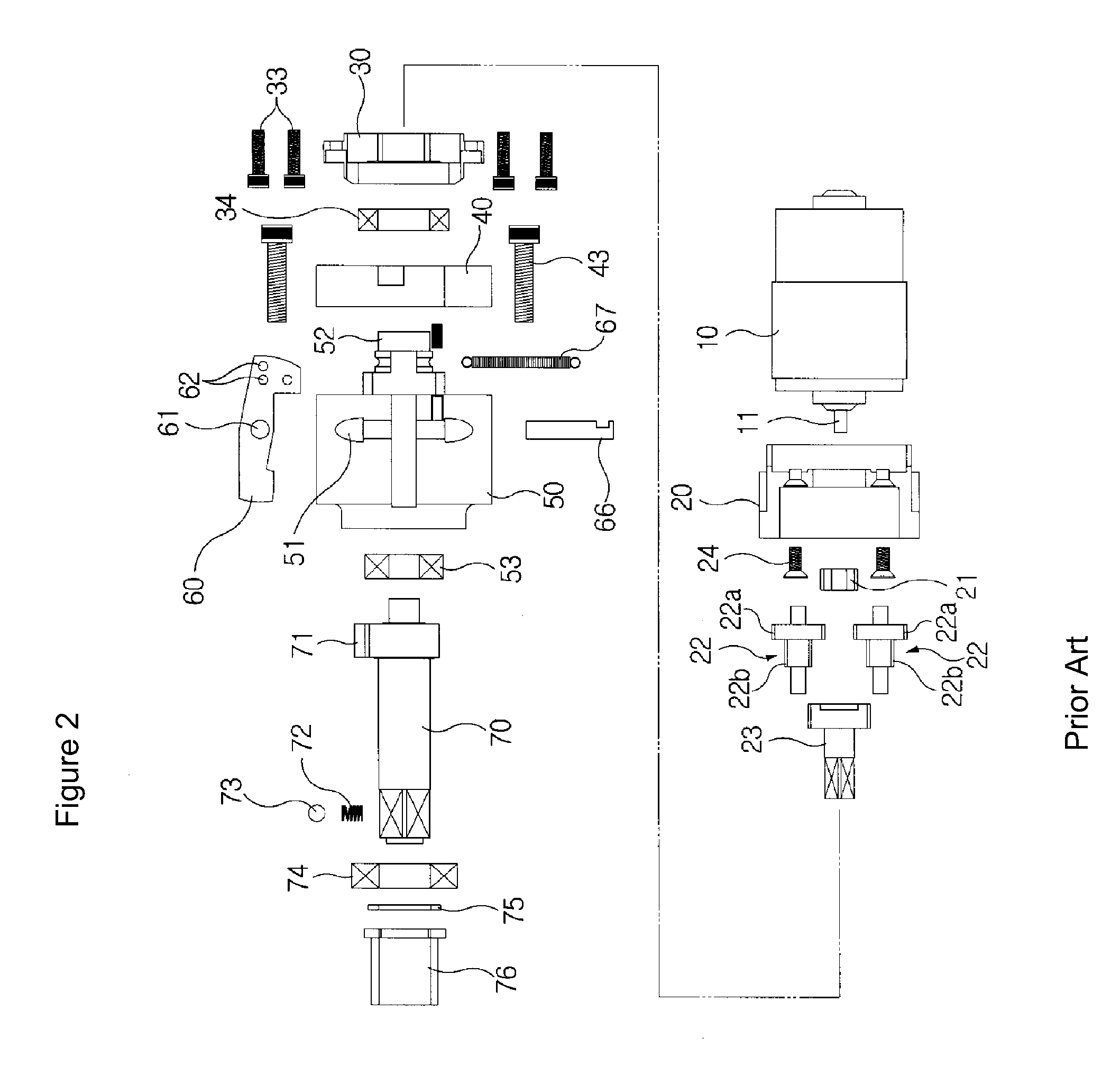
[0053]Meanwhile, the reduction gear may include two or more planetary gears 22. In FIG. 8, the present invention includes two planetary gears 22.
[0054]Here, the rotation shaft 11 of the electric driving motor 10 is connected to the reduction gear. When the sun gear 21 connected to the rotation shaft 11 of the electric driving motor 10 rotates, the first gear 22a of the two planetary gears 22 engaged with the sun gear 21 also rotates. The output gears 23 connected to the second gears 22b of the planetary gear 22 rotate along with the first gears 22a, so as to transmit power to the inertia wheel 50.
[0055]At this time, during transmission of power to the sun gear 21, the planetary gear 22, and the output gear 23, which are designed to have a predetermined gear ratio, when the rotation velocity is lowered, output torque increases. Of course, the gear ratio may be adjusted to generate a desired reduction ratio and output torque.
second embodiment
[0056]Meanwhile, according to the present invention, the planetary gears include three gears which are engaged with the sun gear, in order to obtain a necessary rotation velocity. The operation of the planetary gears can be sufficiently understood with reference to FIG. 9.
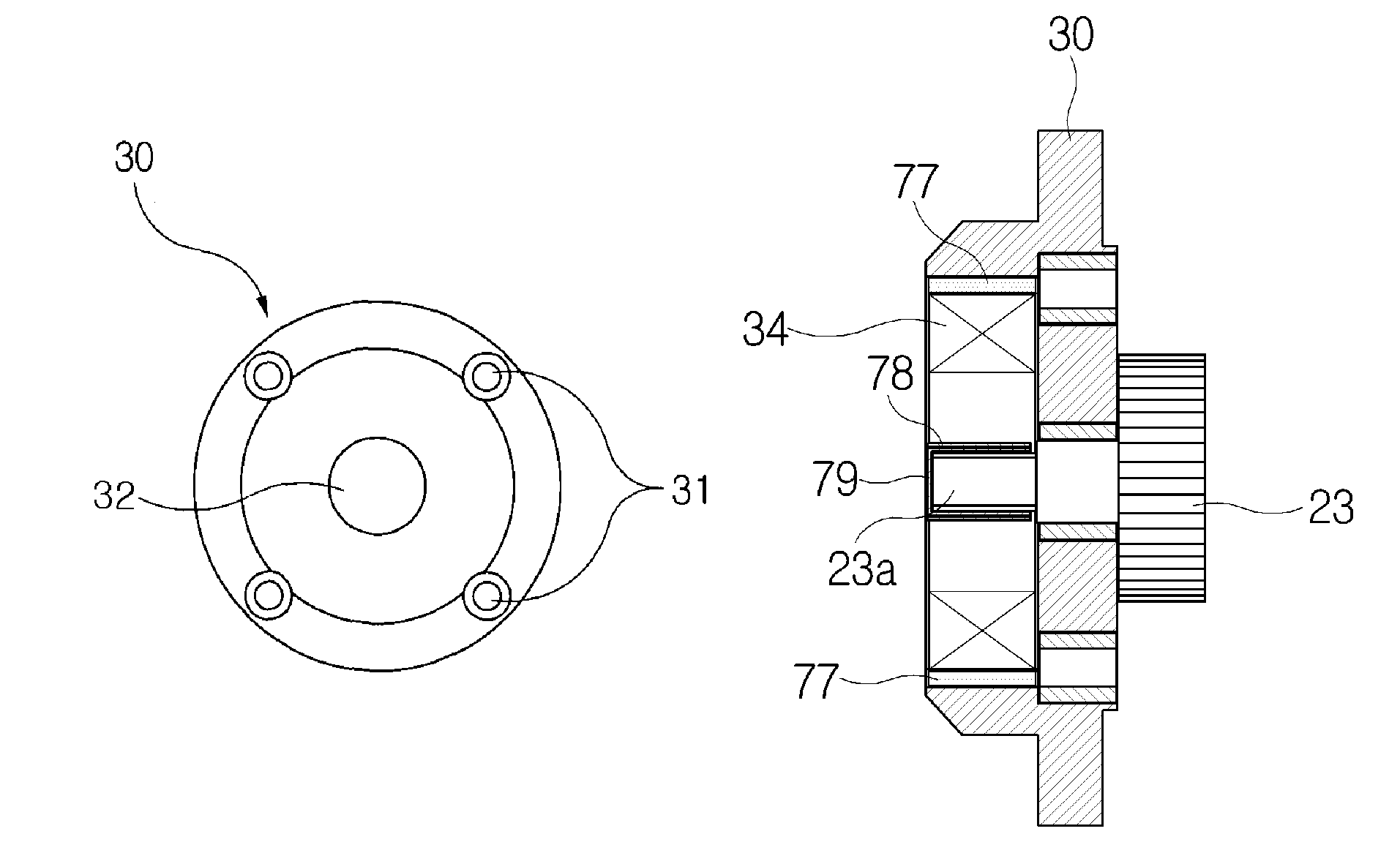
[0057]The inertia wheel 50 has a circular reception groove 54 formed at a side thereof, in which bearings 53 and 74 are received to rotatably support the spindle 70. Therefore, the assembly of the spindle 70 and the inertia wheel 50 is supported at both ends by the bearings 53 and 74. A ball 73 used for coupling the spindle to a socket (not shown) is mounted on a leading end of the spindle 70 and is elastically supported by a spring 72. A washer 75 and bushing 76 may be mounted on an axis of the spindle 70.
[0058]The inertia wheel 50 has a cut portion 55 which is cut lengthwise on an outer peripheral surface. As shown in FIG. 6, the blow body 60 with a desired thickness is received lengthwise between the connection ...
PUM
 Abstract
Description
Claims
Application Information
 - R&D
- Intellectual Property
- Life Sciences
- Materials
- Tech Scout
- Unparalleled Data Quality
- Higher Quality Content
- 60% Fewer Hallucinations
Browse by: Latest US Patents, China's latest patents, Technical Efficacy Thesaurus, Application Domain, Technology Topic, Popular Technical Reports.
© 2025 PatSnap. All rights reserved.Legal|Privacy policy|Modern Slavery Act Transparency Statement|Sitemap|About US| Contact US: help@patsnap.com


