
Staged sodar sounding

a sodar sound and stage technology, applied in the field of sodar methods and apparatuses, can solve the problems of difficult pulse compression techniques, difficult to encode in any effective way, and the energy of the transmitted pulse will swamp the receiver, so as to achieve the effect of effective the same bandwidth and greater simplicity in the design of the receiver system

Inactive Publication Date: 2010-11-16
TELE IP
View PDF12 Cites 3 Cited by
  • Summary
  • Abstract
  • Description
  • Claims
  • Application Information

AI Technical Summary

Benefits of technology

"The invention relates to sodar systems and methods that use encoded transmit pulses to detect echoes from the previous pulse. The number of pulses in a set is determined by the desired range of the sodar system, with two pulses being the minimum number. The coding of the pulses is preferably the same and adapted for matched filter processing. Each pulse is frequency modulated so that its frequency increases or decreases in a linear manner for the duration of the chirp. The range of each pulse is the same, allowing the use of the same matched filter and DSP processes to extract echo data from the received signals. The system should have no gaps in the range, but the dead zone of each pulse can be minimized by alternating between different sets of chirps or using two or more different sets of chirps to fill in the dead-zones of the preceding set. The range dead-zone can also be minimized by using a bandwidth / chirp centre frequency ratio of between 0.1 and 0.2 or time domain matched filtering of received sodar signals."

Problems solved by technology

The basic problem with such techniques is that the pulse must be very short—preferably a few milliseconds—so that the transmit pulse ends before the echoes from short-range anomalies are returned and detected, otherwise the energy of the transmitted pulse will swamp the receiver.
Two problems associated with the use of short pulses: they must have very high energy to achieve an acceptable signal-to-noise ratio [s / n], and they are difficult to encode in any effective way so that pulse-compression techniques are difficult to apply.

Method used


Image

  • Staged sodar sounding
  • Staged sodar sounding
  • Staged sodar sounding

Examples


Embodiment Construction

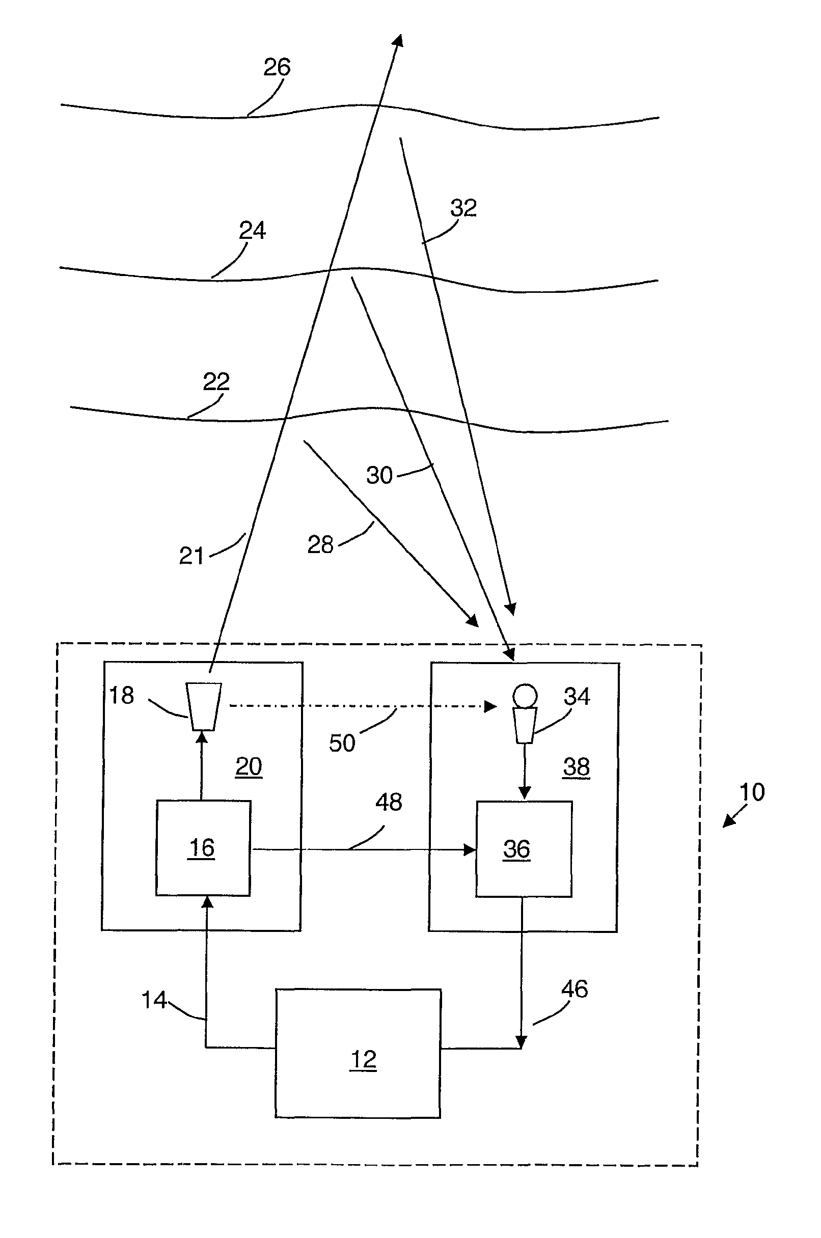
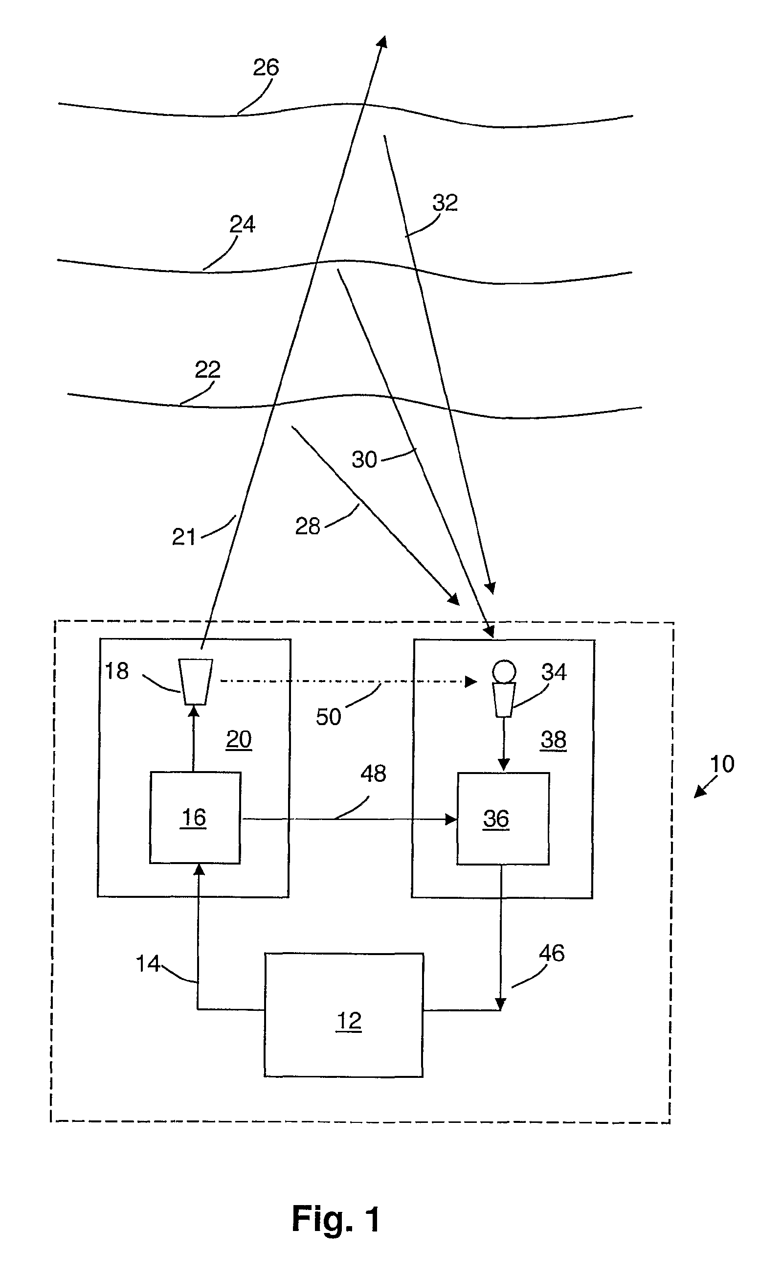
[0023]Before describing the chosen examples, it should be noted that the layout of transmitters and receivers and the processing of the received echoes can conveniently follow the teachings of our prior patent applications mentioned above. In those patent applications we showed how atmospheric anomalies could be graphically indicated, how the speed and bearing of airflow at any desired range (altitude) could be determined and depicted and how other variables such as temperature, humidity, wind-shear and total energy could be estimated or approximated. Accordingly, the description of received signal manipulation using DSP techniques (typically employing Fourier transformations) contained in our prior patent applications is incorporated herein and should be read in conjunction with the following description.

[0024]However, as will be described below, recent developments in acoustic transducers allow significant economies and simplifications with respect to the systems described in our ...


PUM


Abstract

A monostatic sodar system (10) for atmospheric sounding includes a processor and display unit (12) that generates a set of acoustic chirps for transmission by transmitter 20. Discontinuities (22, 24 and 26) result in echoes (28, 30 and 32) being returned to a receiver (38) of system (10). Receiver (38) outputs extracted echo signals on line to the processor (12) for analysis. Detector (36) implements a Fourier domain matched-filter to extract echo signals from noise. By using a set of multiple chirps of increasing length with increasing intervals between them, substantially any feasible range can be accommodated using send-then-listen techniques with the benefit of high s / n performance.

Description

[0001]This is a national phase application in the United States of International Application PCT / AU2006 / 000247 filed 28 Feb. 2006, claiming priority from Australian application number 2005900901 filed 28 Feb. 2005, the disclosures of which are incorporated herein by reference.BACKGROUND OF THE INVENTION[0002]1. Field of the Invention[0003]This invention relates to sodar methods and apparatus for atmospheric sounding using encoded pulses in the transmit-then-listen mode. The techniques of the invention have particular application to so-called ‘monostatic’ sodar configurations in which the receiver(s) is located ‘up-range’ near the transmitter and backscattered echoes are detected by the receiver. However, the methods of the invention are also applicable to so-called ‘bistatic’ sodar configurations where the receiver(s) is located down-range and forward-scattered echoes are detected.[0004]2. Description of Related Art[0005]Transmit-then-listen sodar sounding techniques, in which the t...

Claims


Application Information

Patent Timeline
Patent Type & Authority Patents(United States)
IPC IPC(8): G01S15/12
CPCG01S15/104G01S15/12G01S15/885
Inventor MARTIN, ANDREW LOUIS
Owner TELE IP
Learn More