Rotation mechanism for construction machine and method of measuring backlash in the mechanism

a technology of rotating mechanism and construction machine, which is applied in the direction of mechanical equipment, bearing unit rigid support, hoisting equipment, etc., can solve the problems of reducing the accuracy of digging work, reducing the working accuracy, and affecting the operation of the hoisting machine, so as to achieve the effect of optimizing the positioning of the swing frame and knocking pin, avoiding the effect of substantial reduction of the insertion hole and smooth assembly of the pinion drive devi

Active Publication Date: 2010-11-16
NIHON KENKI CO LTD
View PDF4 Cites 0 Cited by
  • Summary
  • Abstract
  • Description
  • Claims
  • Application Information

AI Technical Summary

Benefits of technology

[0006]The existence of a backlash between an inner gear of an inner race and a pinion causes a front on a swing frame to shake, and hence, leads to a reduction in the working accuracy. When a swing frame, for example, in a hydraulic shovel rattles during digging operation by a bucket, vibrations are transmitted to the bucket via a boom and arm. To the bucket located far apart from the center of its swinging motion, the vibrations are transmitted in a magnified state, thereby causing the bucket to shake to unexpected large extent and reducing the accuracy of the digging work. It is, therefore, desired to fix a center frame and a pinion drive device at appropriate locations such that the backlash between the inner gear and the pinion is minimized as much as possible. Especially in recent years, it is demanded to reduce such a backlash to a minimum need such that a construction machine is improved in the working accuracy or in the comfort of use.

Problems solved by technology

The existence of a backlash between an inner gear of an inner race and a pinion causes a front on a swing frame to shake, and hence, leads to a reduction in the working accuracy.
To the bucket located far apart from the center of its swinging motion, the vibrations are transmitted in a magnified state, thereby causing the bucket to shake to unexpected large extent and reducing the accuracy of the digging work.
To resolve such a problem, it is only necessary to secure the center-frame-positioning knock pin 6 around the center connection line S. This positioning, however, involves a difficulty from the practical viewpoint, because in relation to the modules, tooth numbers and the like of the internal gear and a pinion 4, a bracket for mounting the pinion drive device is generally arranged astride the outer race so that the center frame does not have any sufficient space for the arrangement of the knock pin.
If the diameter of the pinion insertion hole is reduced to increase this space, a great deal of labor is required to insert the pinion and its peripheral elements into the pinion insertion hole without any interference with the circumferential edge portion of the hole upon assembling the pinion drive device, thereby making it impossible to smoothly perform the assembly of the pinion drive device.
When an attempt is made to reduce a backlash, it is impossible to determine how much the backlash has been reduced unless the amount of the backlash is known.

Method used


Image

  • Rotation mechanism for construction machine and method of measuring backlash in the mechanism
  • Rotation mechanism for construction machine and method of measuring backlash in the mechanism
  • Rotation mechanism for construction machine and method of measuring backlash in the mechanism

Examples


Embodiment Construction

[0025]With reference to the drawings, a description will hereinafter be made about a best mode for carrying out the present invention.

[0026]Firstly, the overall construction of the hydraulic excavator mentioned as an illustrative construction machine will be outlined based on FIG. 5.

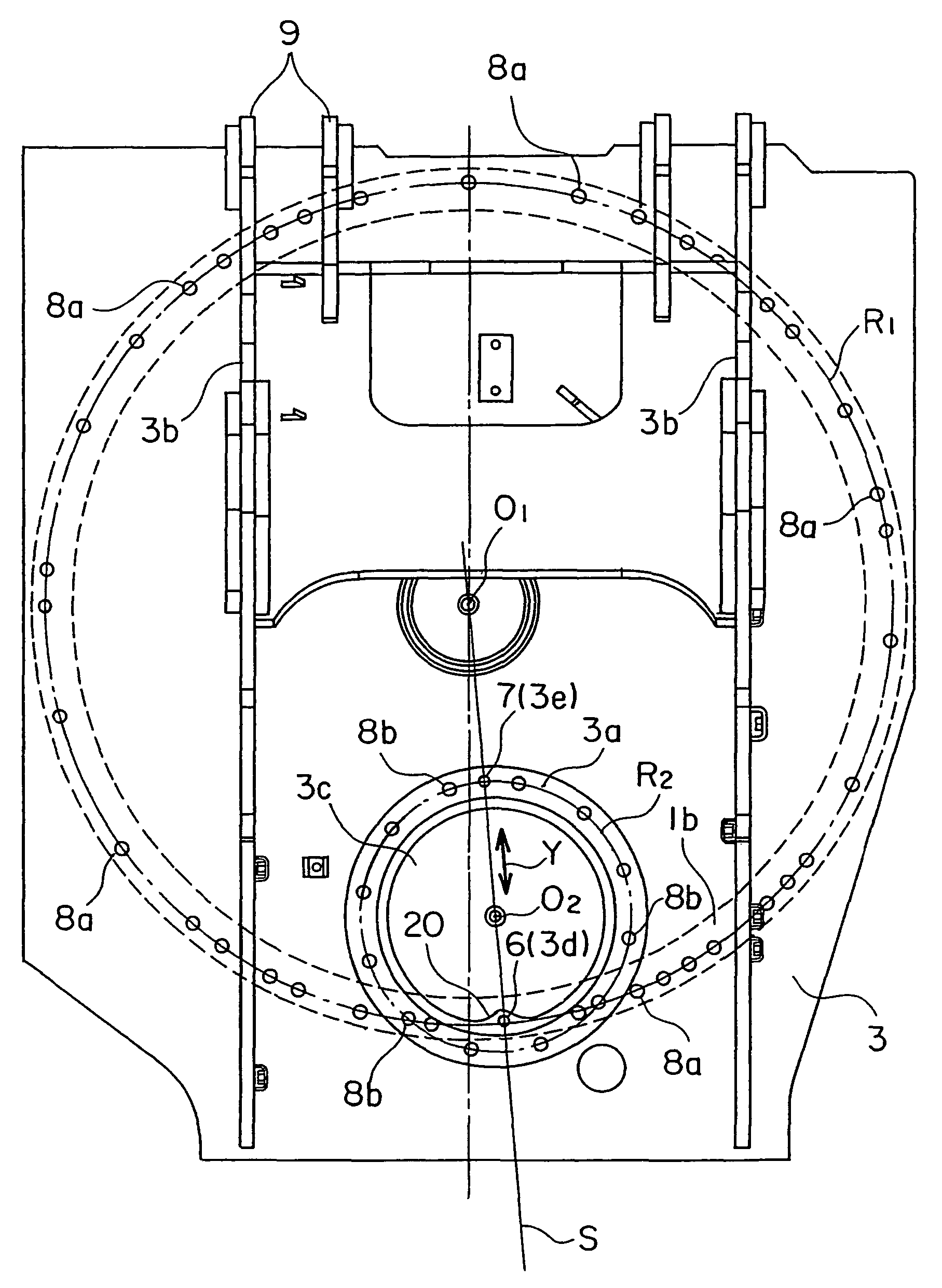
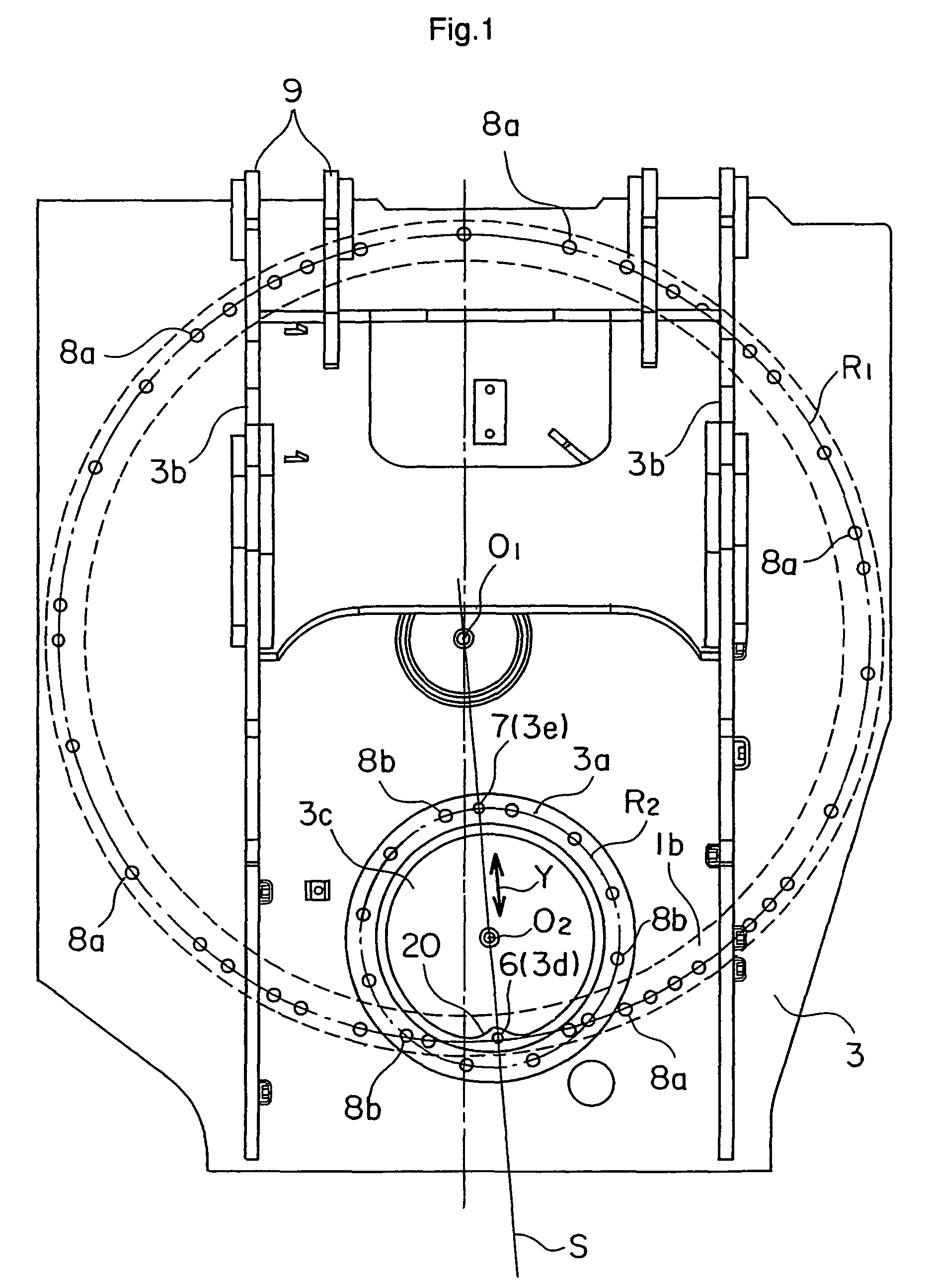
[0027]Depicted are a mobile hydraulic excavator 10 that travels at a work site to perform various work such as digging work and loading work of excavated earth or sand, an undercarriage 11 of the mobile hydraulic excavator 10, said undercarriage serving as a base for mounting thereon an upperstructure 12 and being capable of travelling by crawlers, the upper structure 12 composed of a swing frame 2 and various devices arranged thereon and supported swingably relative to the undercarriage 11 via a swing circle 1, an operator's cab 13 in which an operator performs operations of a front 14 and the like, and the front 14 serving as a working section of the hydraulic excavator 10.

[0028]Arranged on the swing f...


PUM


Abstract

A swing mechanism for a construction machine is provided with a center frame 3 having a pinion insertion hole 3c, an inner race having an internal gear and mounted on a side of an undercarriage, an outer race 1b rotatably arranged surrounding the inner race and provided with the center frame secured thereon by bolts 8a, a pinion maintained in meshing engagement with the internal gear of the inner race, and a pinion drive device. A pin fit-in hole 3d arranged in the center frame 3 such that a knock pin 6 fixed on the outer race 1b is fitted in the pin fit-in hole to position the center frame 3. To arrange the pin fit-in hole 3d in the center frame 3, a pin fit-in hole portion 20 through which the pin fit-in hole 3d is formed is locally arranged such that the pin fit-in hole portion 20 extends toward the pinion insertion hole 3c to have a center of the pin fit-in hole 3d located on a center connection line S. This construction allows to perform smooth assembly of the pinion drive device while enabling to optimally arrange the knock pin for positioning the center frame.

Description

TECHNICAL FIELD[0001]This invention relates to a swing mechanism for a construction machine such as a hydraulic excavator or crane, which is provided with a swing frame, an inner race having an internal gear and mounted on a side of a base such as an undercarriage, an outer race rotatably arranged surrounding the inner race and provided with the swing frame secured thereon by bolts, a pinion maintained in meshing engagement with the internal gear of the inner race, and a pinion drive device for rotationally driving the pinion, and also to a method for measuring its backlash.BACKGROUND ART[0002]Construction machines such as hydraulic excavators include those constructed such that a swing frame and an upperstructure, which is arranged on the swing frame and is composed of various devices, can be caused to swing relative to a base such as an undercarriage. The term “swing mechanism for a construction machine” means a mechanism constructed by arranging a swing frame, an inner annular ri...

Claims


Application Information

Patent Timeline
Patent Type & Authority Patents(United States)
IPC IPC(8): F16H57/02B66C23/84E02F9/12F16C35/077
CPCE02F9/121Y10T74/19851Y10T74/19898Y10T74/19623E02F9/0808E02F9/123E02F9/267E02F9/12
Inventor NOZUE, AKIYASUTANAKA, NOZOMUISOBE, HIROYUKI
Owner NIHON KENKI CO LTD
Why Eureka
Try Eureka