
Effective wear-leveling and concurrent reclamation method for embedded linear flash file systems

a linear flash file system and wear leveling technology, applied in the field of reclamation of memories, can solve the problems of flash memory being erased, expensive, subject to breakdown, old data on a hard disk can simply be overwritten,

Inactive Publication Date: 2010-11-09
HONEYWELL INT INC
View PDF13 Cites 55 Cited by
  • Summary
  • Abstract
  • Description
  • Claims
  • Application Information

AI Technical Summary

Benefits of technology

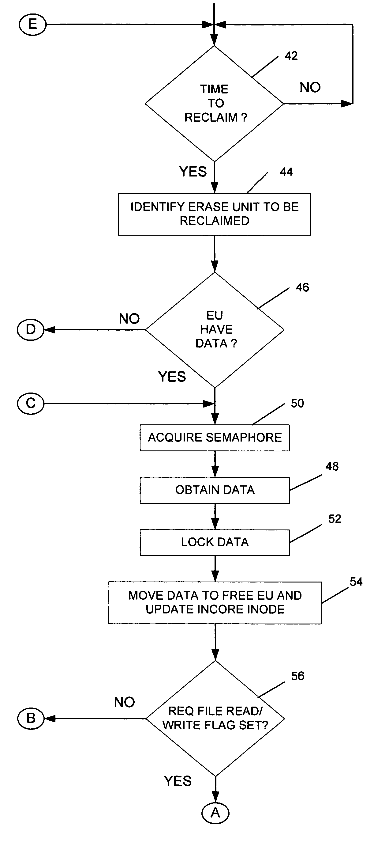
The present invention provides methods for reclaiming individual parts of a memory and performing file operations simultaneously. The methods involve suspending the reclamation operation to perform the file operation and then resuming it afterwards. Additionally, the invention provides methods for selecting specific parts of the memory for reclamation based on their fitness for reclamation, even if they do not contain dirty blocks. These methods improve the efficiency and performance of flash memories by optimizing their reclamation process.

Problems solved by technology

Flash memory reduces the need for separate magnetic disk drives, which can be bulky, expensive, and subject to breakdown.
One disadvantage of flash memory in comparison to other memories such as hard disks is that flash memory must be erased before it can be reprogrammed, while old data on a hard disk can simply be over-written when new information is to be stored thereon.
Thus, when a file which is stored in flash memory changes, the changes are not written over the old data but are rather written to one or more new free blocks of the flash memory, and the old data is marked unavailable, invalid, or deleted, such as by changing a bit in a file header or in another control unit stored on the flash memory.
Conventional flash file systems do not permit file transactions during reclamation.
Accordingly, if a reclamation is underway when a power interruption occurs, valuable data could be lost since the time that any power backup is effective is limited and may be exceeded by the time required to finish the reclamation.
Furthermore, reclamation in current flash memory file systems is based only on emulating the hard disk on linear flash without considering the rapid and deterministic storage requirements of real-time embedded applications and also without considering flash life because of (a) block device nature emulating the hard disk and (b) in-efficient wear-leveling algorithms.

Method used


Image

  • Effective wear-leveling and concurrent reclamation method for embedded linear flash file systems
  • Effective wear-leveling and concurrent reclamation method for embedded linear flash file systems
  • Effective wear-leveling and concurrent reclamation method for embedded linear flash file systems

Examples


Embodiment Construction

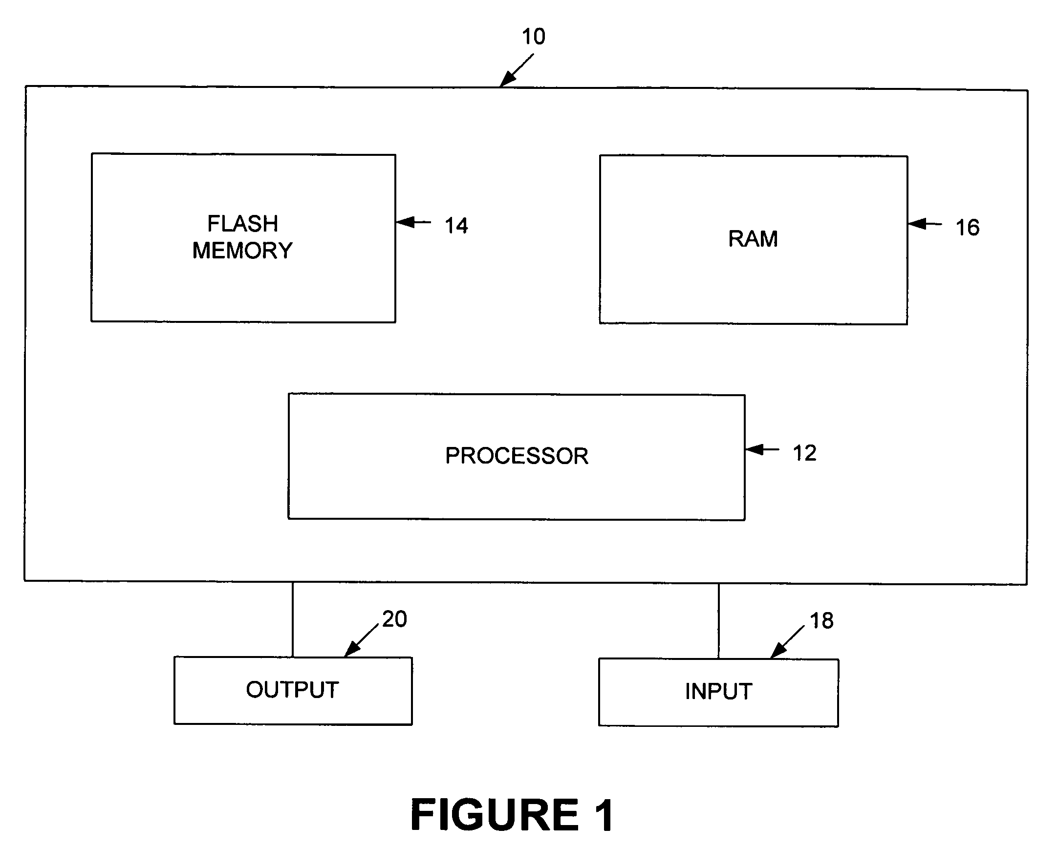
[0021]FIG. 1 shows an embedded system 10 which can be a computer, a personal digital assistant, a telephone, a printer, etc. The embedded system 10 includes a processor 12 that interacts with a flash memory 14 and a RAM 16 to implement the functions provided by the embedded system 10.

[0022]Additionally, the embedded system 10 includes an input device 18 and an output device 20. The input device 18 may be a keyboard, a keypad, a mouse or other pointer device, a touch screen, and / or any other device suitable for use by a user to provide input to the embedded system 10. The output device 20 may be a printer, a display, and / or any other device suitable for providing output information to the user of the embedded system 10.

[0023]A number of definitions are useful to understand at the outset and can be referred to as the present invention is described below.

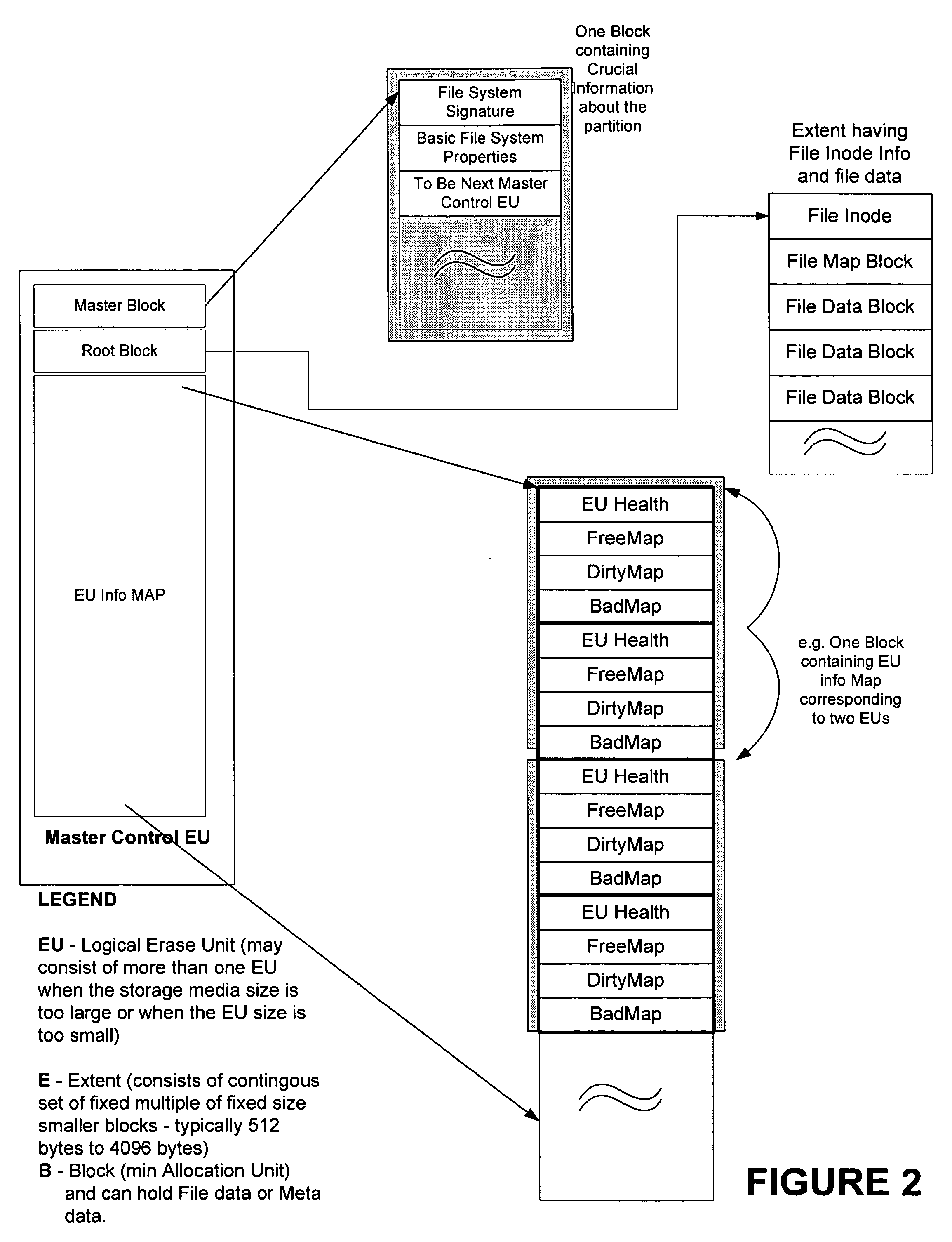
[0024]Block—A linear flash storage device such as the flash memory 14 typically contains a plurality of Erase Units. An Erase Unit is...


PUM


Abstract

Reclamation of an Erase Unit of a flash memory is performed concurrently with a file operation on the flash memory by initiating a reclamation operation on the individually erasable portion of the memory, by suspending the reclamation operation for the file operation, by performing the file operation, and by resuming the reclamation operation.

Description

TECHNICAL FIELD OF THE INVENTION[0001]The present invention relates to the reclamation of memories such as flash memories.BACKGROUND OF THE INVENTION[0002]Flash memory (e.g., Electrically-Erasable Programmable Read-Only Memory or “EEPROM”) has been used as long-term memory in computers, printers, and other instruments. Flash memory reduces the need for separate magnetic disk drives, which can be bulky, expensive, and subject to breakdown.[0003]A flash memory typically includes a large plurality of floating-gate field effect transistors arranged as memory cells, and also includes circuitry for accessing the cells and for placing the transistors in one of two memory conditions (0 or 1). These transistors retain information even when power is removed, and their memory conditions can be erased electrically while the flash memory is in place.[0004]One disadvantage of flash memory in comparison to other memories such as hard disks is that flash memory must be erased before it can be repro...

Claims


Application Information

Patent Timeline
Patent Type & Authority Patents(United States)
IPC IPC(8): G06F12/02
CPCG06F3/0616G06F3/064G06F3/0679G06F12/0246G06F2212/1036G06F2212/7211G06F2212/7205
Inventor PANDIT, ANIL KUMARSAMPATH, SRIDHAR
Owner HONEYWELL INT INC
Learn More