
Electrical connector terminal having two contact portions and two leaning portions extending from a base

a technology of electrical connectors and terminals, which is applied in the direction of electrical apparatus, connection, coupling device connection, etc., can solve the problems of affecting the electrical connection between the chip module and the electrical connector, the movement distance of the pin pushing the two blocking posts is too small, and the two force arms are short, so as to achieve the effect of large movement distance and improved flexibility

Inactive Publication Date: 2010-11-09
LOTES
View PDF5 Cites 14 Cited by
  • Summary
  • Abstract
  • Description
  • Claims
  • Application Information

AI Technical Summary

Benefits of technology

[0012]One object of the present invention is to provide a terminal with improved flexibility and large movement distance and an electrical connector using the same.
[0014]Compared with the prior art, the two flexible arms of the terminal respectively have a leaning portion that faces to each other to contact the pin of the chip module. The force arm providing elastic deformation becomes longer. Therefore, the flexibility of the force arm is increased. The pin of the chip module being deformed is avoided and the usage life of the terminal of the electrical connector is improved. Moreover, the movement distance of the force arm also becomes larger so as to guarantee normal electrical connection between the chip module and the electrical connector.

Problems solved by technology

The drawbacks of the electrical connector are:
However, the pin contacts most part of the two blocking posts, the two force arms are short.
The movement distance of the pin pushing the two blocking posts is too small.
The pins will not electrically connect the terminals normally, as a result, it will affect the electrical connection between the chip module and the electrical connector.

Method used


Image

  • Electrical connector terminal having two contact portions and two leaning portions extending from a base
  • Electrical connector terminal having two contact portions and two leaning portions extending from a base
  • Electrical connector terminal having two contact portions and two leaning portions extending from a base

Examples


Embodiment Construction

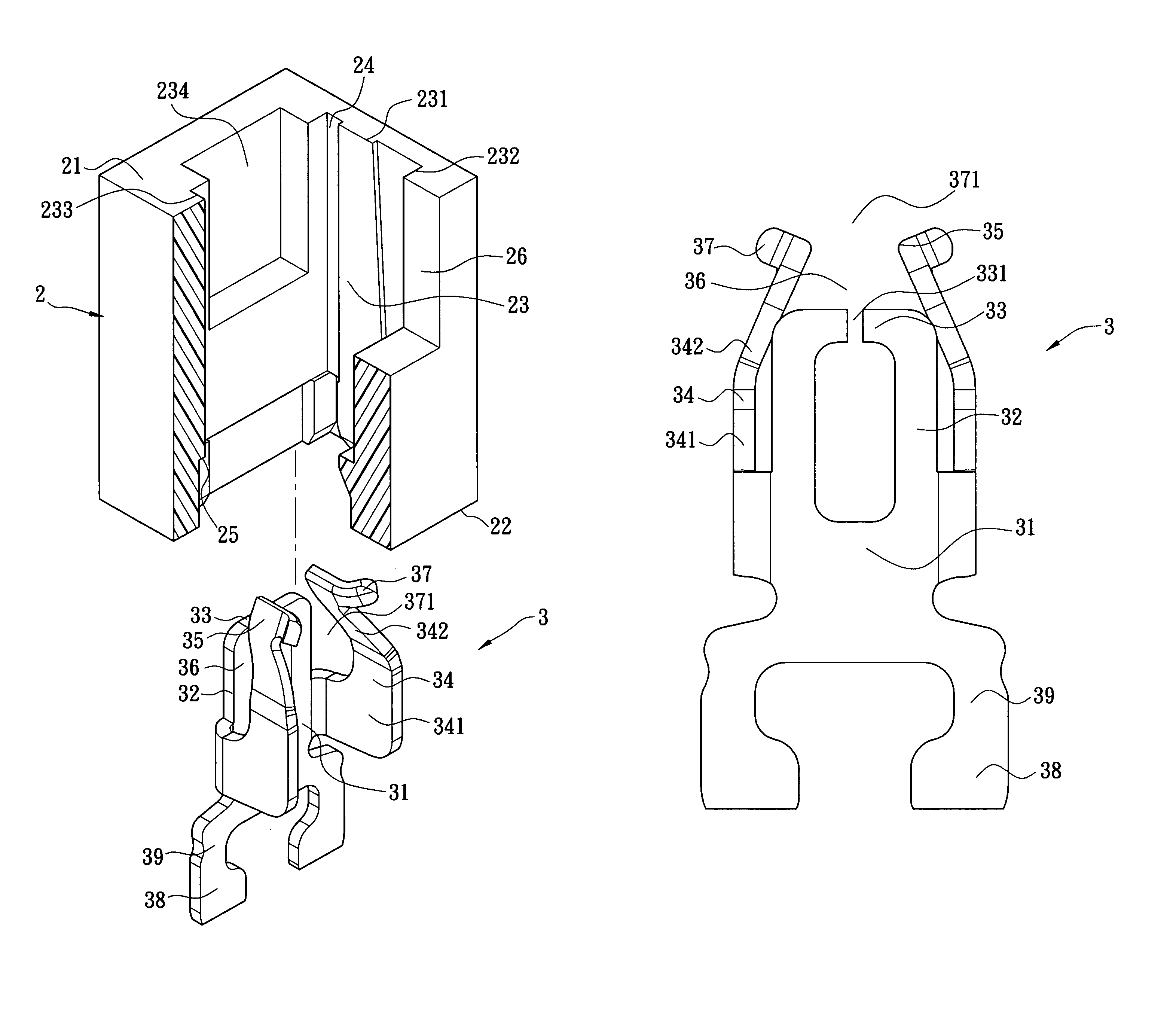
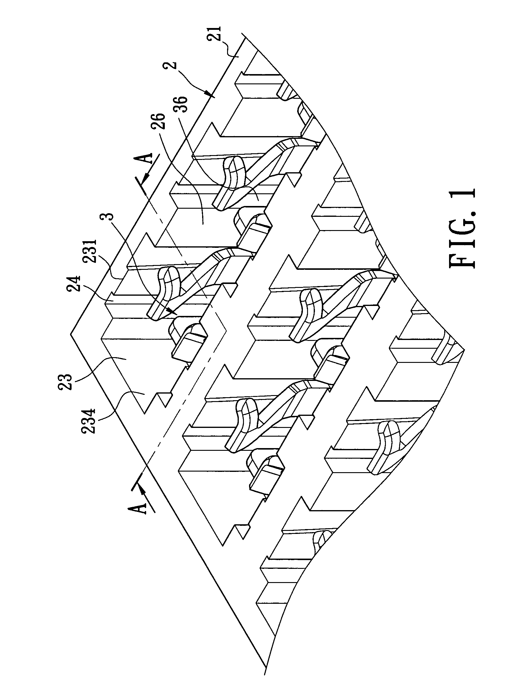
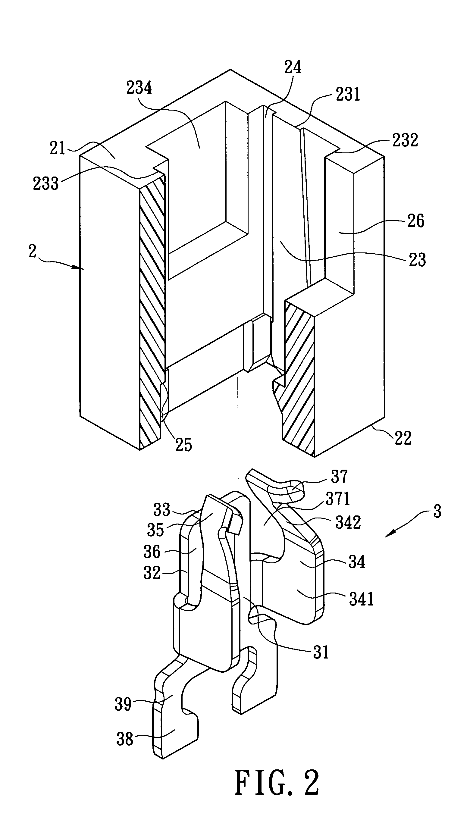
[0023]Reference is made to FIGS. 1 to 6, which is the electrical connector and the terminal thereof according to the first embodiment of the present invention. The electrical connector is used for electrically connecting a chip module (not shown in the figure). The chip module has a plurality of pins 1. The electrical connector includes a main body 2 and a plurality of terminals 3. Because the dimension of the electrical connector is large, part of the electrical connector is shown in the figure to clearly illustrate the content of the present invention.

[0024]The main body 2 has an upper surface 21, a lower surface 22 opposite to the upper surface 21, and a plurality of receiving holes 23 that pass through the upper surface 21 and the lower surface 22. The receiving holes 23 are disposed at matrix and intervals.

[0025]Each receiving hole 23 has a first side wall 231, a second side wall 232, a third side wall 233 and a fourth side wall 234. The first side wall 231 and the third side w...


PUM


Abstract

An electrical connector and a terminal thereof are disclosed. The base portion of the terminal extends upwards to form two flexible arms. Each of the two flexible arms extends towards each other to form a leaning portion. There is a gap between the two leaning portions. Two arm portions extend from two sides of the base portions. The two arm portions respectively have a contact portion. The two contact portions and the two leaning portions are disposed at a front location and a rear location. The two leaning portions and the two contact portions surround to form a receiving space. The present invention can prevent the pins of the chip module from being deformed, improve the usage life of the terminals, and assure that the chip module is electrically connected with the electrical connector.

Description

BACKGROUND OF THE INVENTION[0001]1. Field of the Invention[0002]The present invention relates to an electrical connector and a terminal thereof, particularly relates to an electrical connector and a terminal thereof used for connecting the pins of an inserted chip module.[0003]2. Description of Related Art[0004]Electrical connectors are used for electrically connecting a chip module having a plurality of pins. The electrical connector includes a main body and a plurality of terminals received in the main body.[0005]The main body has an upper surface, a lower surface opposite to the upper surface, and a plurality of receiving holes that pass through the upper surface and the lower surface.[0006]The terminals are respectively received in the receiving holes. Each of the terminals has a base portion positioned in the receiving hole. Two sides of the base portion extend upwards and forwards to form two arm portions. The two arm portions are located in the receiving holes, and the two ar...

Claims


Application Information

Patent Timeline
IPC IPC(8): H01R11/22
CPCH01R13/112H01R13/193
Inventor JU, TED
Owner LOTES
Learn More