
Power tool safety mechanisms

a safety mechanism and power tool technology, applied in the direction of metal sawing accessories, instruments, slip couplings, etc., can solve the problem that the trigger mechanism may cut power to the active portion of the tool

Inactive Publication Date: 2010-11-09
BLACK & DECKER INC
View PDF40 Cites 63 Cited by
  • Summary
  • Abstract
  • Description
  • Claims
  • Application Information

AI Technical Summary

Benefits of technology

Enhances safety by accurately detecting operator proximity and contact, triggering timely protective actions to prevent injuries, thereby improving the safety of power tool operations.

Problems solved by technology

However, some power tools preclude the use of a guard that would effectively prevent the operator from making contact with the active portion of the tool.
If the trigger is disengaged when the power tool is operating, the trigger mechanism may cut power to the active portion of the tool.
Second, proximate detection subsystems utilize various sensing techniques to determine the proximity of the operator to the active portion of the power tool.
Third, contact detection subsystems generally employ various capacitive sensing techniques to determine when the operator physically touches the active portion of the power tool.

Method used


Image

  • Power tool safety mechanisms
  • Power tool safety mechanisms
  • Power tool safety mechanisms

Examples


second embodiment

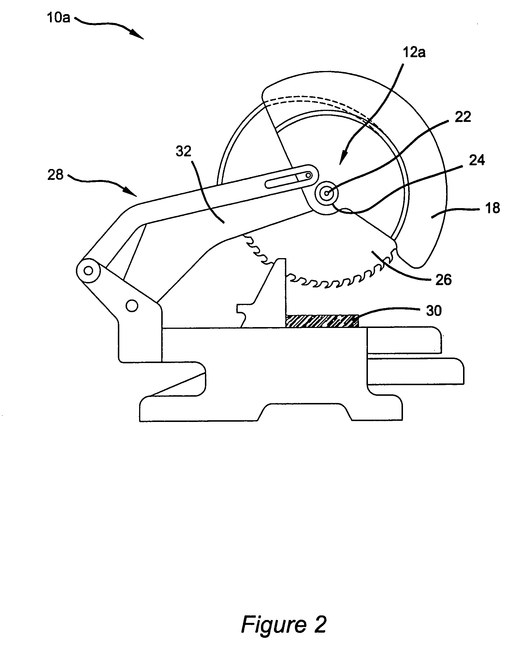
[0150]With reference to FIG. 3 a power tool 10b employing a sensing mechanism 12b according to the present invention is shown. The exemplary power tool embodied herein is a miter saw, however it is appreciated that the safety system of the present invention may be adapted for use with a variety of power tools. Miter saw 10b generally comprises a base portion 40, an angularly movable table assembly 42, and an angularly movable housing assembly 44 having a pivotally attached drive assembly 46. The drive assembly 46 is generally comprised of an electrical motor 48 drivingly coupled by way of an extension arm 50 to saw blade 52. Positioned at the distal end of the arm 50 is saw blade 52 and a handle portion 54 for controlling articulation of the saw blade 52 to engage a workpiece. The base portion 40 of the miter saw 10b includes a fence portion 56 for positioning a workpiece relative to the saw blade 52. The electrical motor 48 of the power tool 10b is activated by a trigger mechanism ...

first embodiment

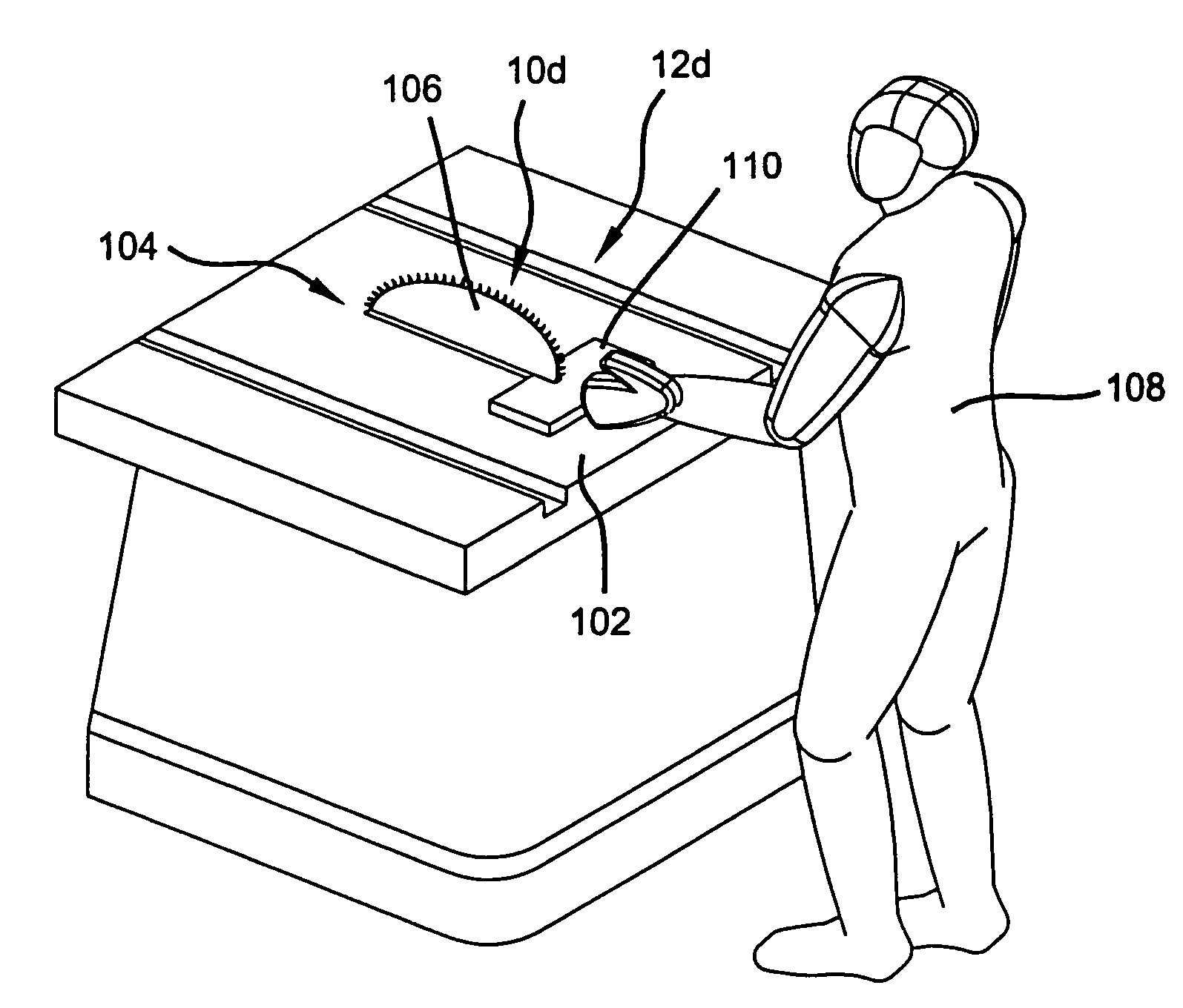
[0183]Contrary to the first embodiment, the following is a description of an alternate sensing mechanism 12e hereinafter referred to as proximity sensing. Whereas the previous circuit triggered on the lack of a signal, the following will trigger on the presence of a signal. FIG. 15 illustrates a known capacitive sensing system 160. In system 160 a transmitter 162 is connected to the handle or trigger portion of the tool 164 and broadcasts a signal. The signal is capacitively coupled to the operator 170. The receiver 172 is connected to the active portion of the tool 174. When the operator 170 is holding the tool correctly, the signal is transmitted through the person 170 to the receiver 172. As the operator 170 approaches the active portion of the tool 174, the signal intensity on the receiver 172 increases until some predetermined level is reached. At that point a predetermined action is performed, such as braking of motor / blade or other safety mechanism 14 disclosed herein to prev...

third embodiment

[0371]a brake is shown in FIG. 94. The brake 1750 includes a wedge or panel brake 1752 adapted to engage the saw blade 1650. Upon activation of the brake 1750, push arm 1722 forces wedge 1752 into blade 1650. As wedge 1752 engages the saw blade 1650, the wedge 1752 engages the teeth of blade 1650. The wedge shape of wedge 1752 causes it to be drawn into further engagement with the saw blade 1650, until the saw blade 1650 is stopped.


PUM


Abstract

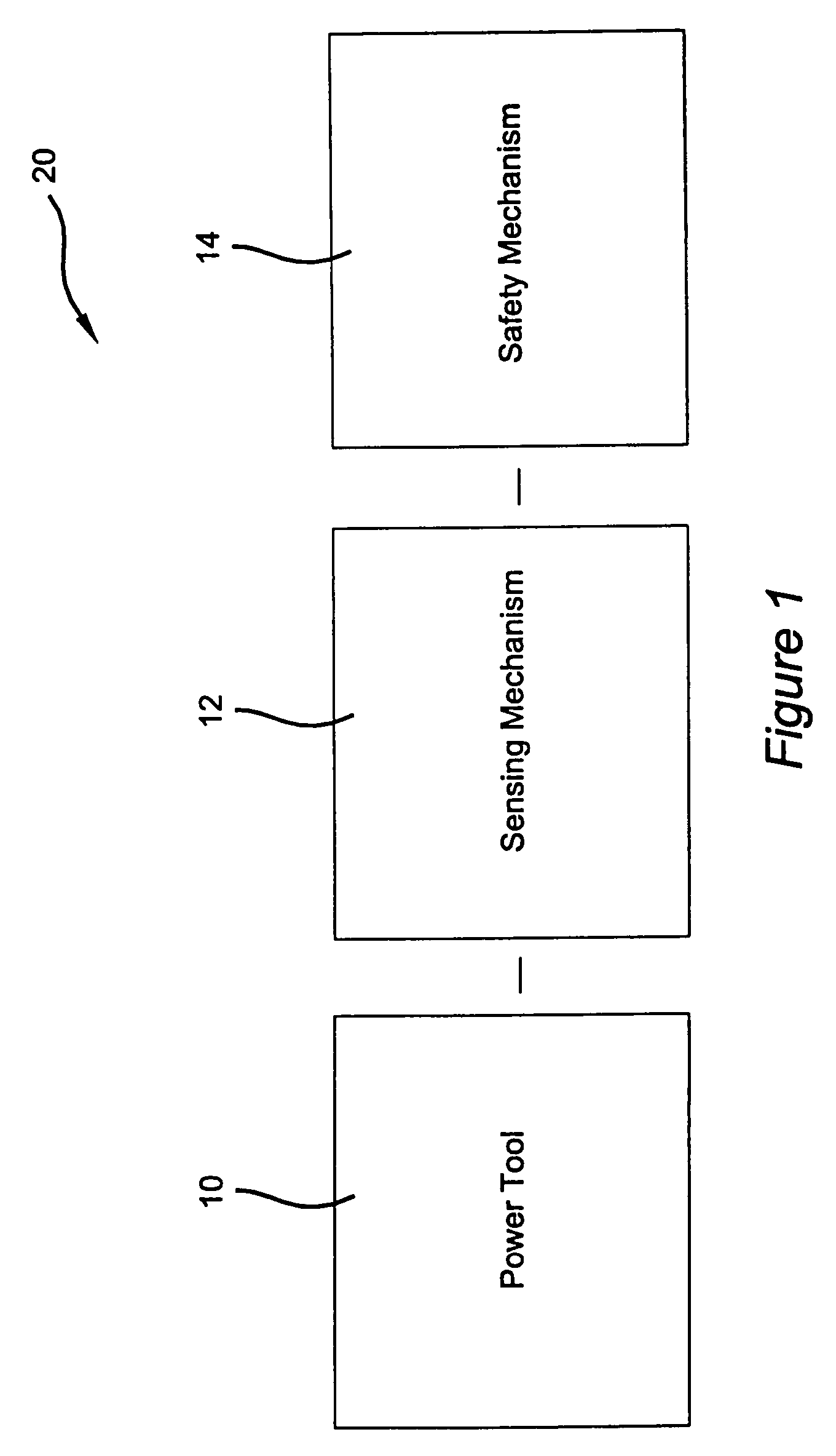
A sensing mechanism (12) for detecting user contact with an active portion (26) of the power tool (10) is provided. In addition, a safety mechanism (14) for preventing prolonged user contact with the active portion (26) of a power tool (10) is provided. The safety mechanism (14) is configured to actuate upon receipt of a signal from the sensing mechanism (12). According to a first aspect, the safety mechanism (14) is arranged to rapidly displace the active portion (26) away from a user extremity. Alternatively, according to a second aspect, the safety mechanism (14) is arranged to rapidly urge an extremity of the user away from the active portion (26) of the power tool (10).

Description

CROSS-REFERENCE TO RELATED APPLICATIONS[0001]This application is a divisional of U.S. patent application Ser. No. 10 / 753,845, filed Jan. 8, 2004, now U.S. Pat. No. 7,373,863 which is a continuation of International Application No. PCT / US02 / 21790, filed on Jul. 11, 2002. This application also claims the benefit of U.S. Provisional Application No. 60 / 304,614, filed on Jul. 11, 2001; U.S. Provisional Application No. 60 / 309,352, filed on Aug. 1, 2001; U.S. Provisional Application No. 60 / 323,511, filed Sep. 19, 2001; U.S. Provisional Application No. 60 / 340,191, filed Dec. 14, 2001, and U.S. Provisional Application No. 60 / 340,612, filed Dec. 14, 2001.FIELD OF INVENTION[0002]The present invention relates generally to a safety system for a power tool and, more particularly to various improved safety systems for a woodworking power tool that prevents or reduces potentially injurious contact between an active portion of the power tool and a portion of the operators body.BACKGROUND OF THE INVE...

Claims


Application Information

Patent Timeline
Patent Type & Authority Patents(United States)
IPC IPC(8): B23Q15/00B23D47/08B23D47/10B23D59/00B23Q11/04B23Q11/06B27B5/32B27B5/38B27G19/02B27G21/00F16P3/06F16P3/12F16P3/14
CPCB23D47/08F16P3/144B23D59/001B23Q11/06B27B5/32B27B5/38B27G19/02B27G21/00F16P3/06F16P3/12F16P3/14F16P3/148F16P3/141B23D47/10Y10S83/01Y10T83/541Y10T83/162Y10T83/091Y10T83/081Y10T83/141Y10T83/178Y10T83/606Y10T83/089B26D7/24
Inventor CARRIER, DAVID A.
Owner BLACK & DECKER INC
Learn More