
Method and apparatus for an aerodynamic stability management system

a technology of aerodynamic stability and management system, which is applied in the direction of engine starters, instruments, machines/engines, etc., can solve the problems of gas turbine engines stalling primarily, limited range of operation of gas turbine engines, and performance drop

Active Publication Date: 2010-11-09
GENERAL ELECTRIC CO
View PDF29 Cites 30 Cited by
  • Summary
  • Abstract
  • Description
  • Claims
  • Application Information

AI Technical Summary

Benefits of technology

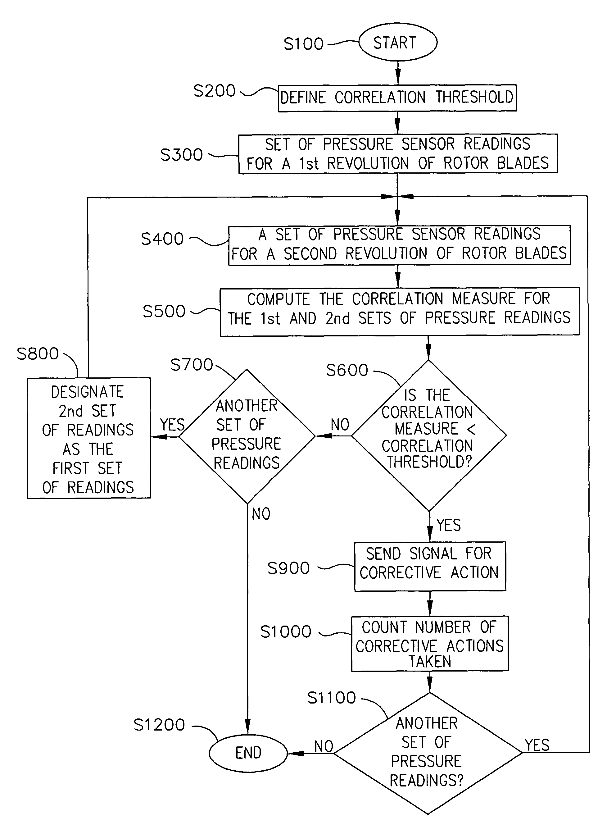
[0004]In one exemplary embodiment, a method for using an aerodynamic stability management system is disclosed. The method includes placing at least one pressure sensor in a compressor, the at least one pressure sensor communicating with an aerodynamic stability management system controller and monitoring gas turbine engine performance using the aerodynamic stability management system controller. The controller includes a memory, an input/output interface and a processor. The method also includes defining a correlation threshold value and calculating a correlation measure using a plurality of pressure signals generated by the at least one pressure sensor and comparing the correlation measure wi

Problems solved by technology

Gas turbine engines have limited ranges of operation due to aerodynamic phenomena that occur in the compressor system such as rotating stall.
Rotating stall manifests itself as a region of severely reduced flow that rotates at a fraction of the compressor rotational speed and causes a drop in performance.
Gas turbine engines stall primarily due to sudden acceleration, pressure distortion and / or engine degradation.
Sudden acceleration is caused by feeding an excessive amount of fuel to the gas turbine engine.
Pressure distortion is caused when an operator takes corrective or evasive action and the gas turbine engine inlet experiences irregular air flow pressure.
Additionally, there is currently no means to intelligently govern engine maintenance and to sense for missing rotor blades.
Engine stall affects operational safety and damages engine equipment causing maintenance costs and engine degradation to increase.

Method used


Image

  • Method and apparatus for an aerodynamic stability management system
  • Method and apparatus for an aerodynamic stability management system
  • Method and apparatus for an aerodynamic stability management system

Examples


Embodiment Construction

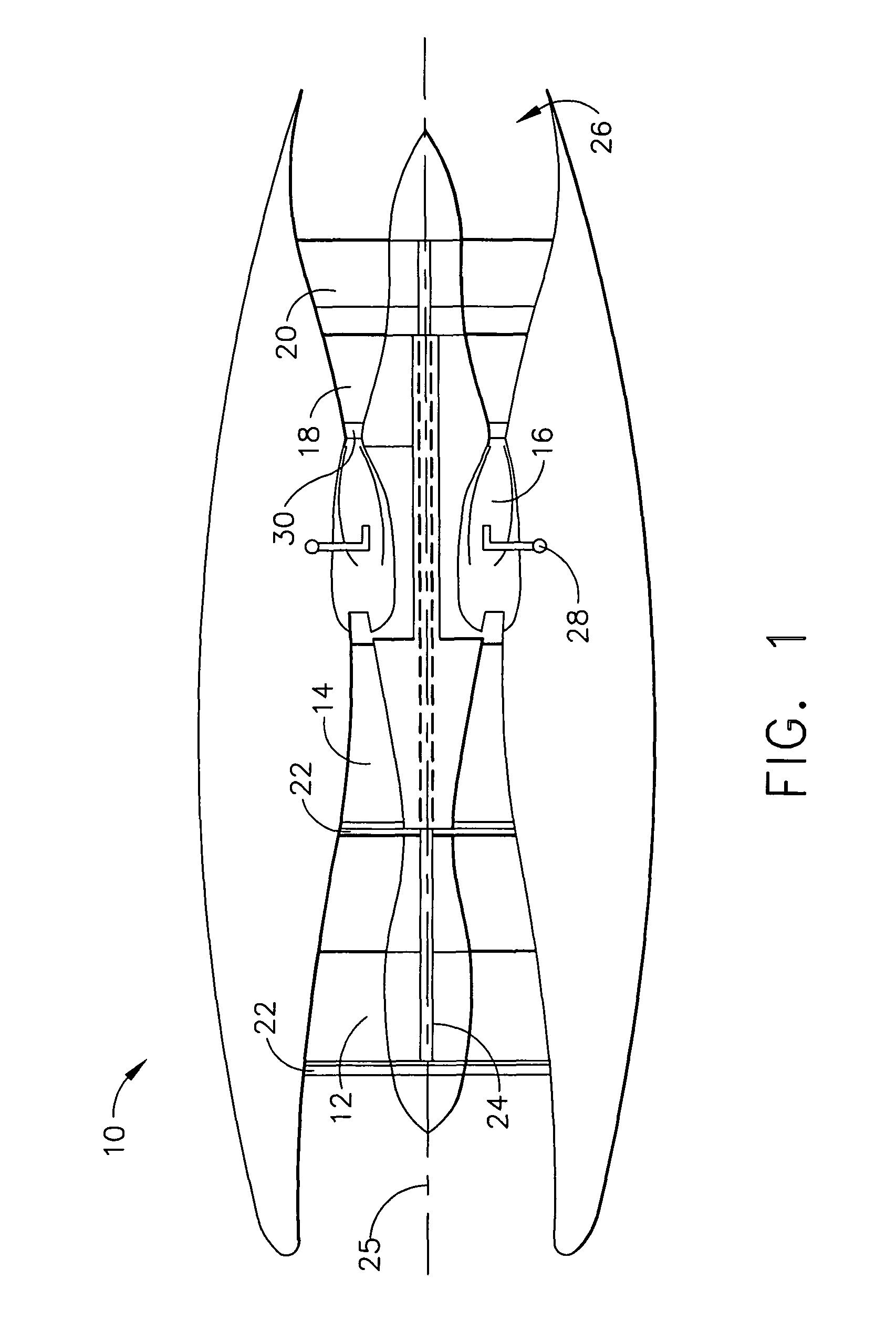
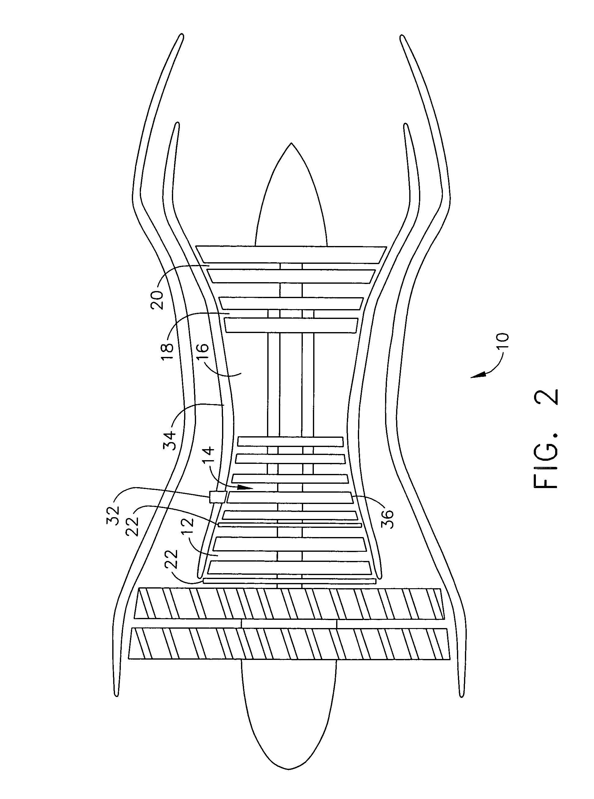
[0015]FIG. 1 shows a schematic illustration of a gas turbine engine 10 including a low pressure compressor 12, a high pressure compressor 14 and a combustor 16. The gas turbine engine 10 also includes a high pressure turbine 18, a low pressure turbine 20 and a turbine nozzle assembly 30.

[0016]In operation, air flows through the low pressure compressor 12 and compressed air is supplied from low pressure compressor 12 to high pressure compressor 14. Each of the low pressure compressor 12 and the high pressure compressor 14 includes variable stator vanes 22 that control the incidence angle of the air as it enters the compressor 12, 14, allowing the gas turbine engine 10 to operate more efficiently. Variable stator vanes 22 effectively take the swirl out of the air and redirect the air to optimize engine 10 performance. A conventional fuel system 28 provides fuel that is combined with high pressure air and burned in the combustor 16. The resulting high temperature combustion gases are d...


PUM


Abstract

A method for using an aerodynamic stability management system is disclosed. The method includes placing at least one pressure sensor in a compressor, the at least one pressure sensor communicating with an aerodynamic stability management system controller and monitoring gas turbine engine performance using the aerodynamic stability management system controller. The controller includes a memory, an input / output interface and a processor. The method also includes defining a correlation threshold value and calculating a correlation measure using a plurality of pressure signals generated by the at least one pressure sensor and comparing the correlation measure with the correlation threshold value. When the correlation measure is less than the correlation threshold value a corrective action is implemented.

Description

BACKGROUND OF THE INVENTION[0001]This invention relates generally to gas turbine engines, and more particularly, to methods and apparatus to facilitate stall avoidance of gas turbine engines using an aerodynamic stability management system.[0002]Gas turbine engines have limited ranges of operation due to aerodynamic phenomena that occur in the compressor system such as rotating stall. Rotating stall manifests itself as a region of severely reduced flow that rotates at a fraction of the compressor rotational speed and causes a drop in performance. Gas turbine engines stall primarily due to sudden acceleration, pressure distortion and / or engine degradation. Sudden acceleration is caused by feeding an excessive amount of fuel to the gas turbine engine. Pressure distortion is caused when an operator takes corrective or evasive action and the gas turbine engine inlet experiences irregular air flow pressure. Currently, engine fuel scheduling is developed through many trials and error, inc...

Claims


Application Information

Patent Timeline
IPC IPC(8): F02C9/20F02C9/50
CPCF01D17/162F02C7/057F02C9/22F02K1/165F04D27/0246F05D2270/101F05D2270/3011F05D2270/301
Inventor WADIA, ASPI RUSTOMCHRISTENSEN, DAVID K.BREEZE-STRINGFELLOW, ANDREWCHUNG, KIYOUNGWISEMAN, MATTHEW WILLIAMSZUCS, PETER NICHOLAS
Owner GENERAL ELECTRIC CO
Learn More