
Fluid shovel apparatus and method

a shovel and flue technology, applied in the direction of snow cleaning, railway cleaning, turf growing, etc., can solve the problems of reducing the service life of the shovel, requiring significant work and effort to overcome the frictional force, and not completely removing the loose material from the support surface, so as to achieve the elimination of the friction between the material and the blade, easy lifting and lifting loose material, and less energy and effort

Inactive Publication Date: 2010-11-02
NAGAMATSU BRIAN H +1
View PDF47 Cites 13 Cited by
  • Summary
  • Abstract
  • Description
  • Claims
  • Application Information

AI Technical Summary

Benefits of technology

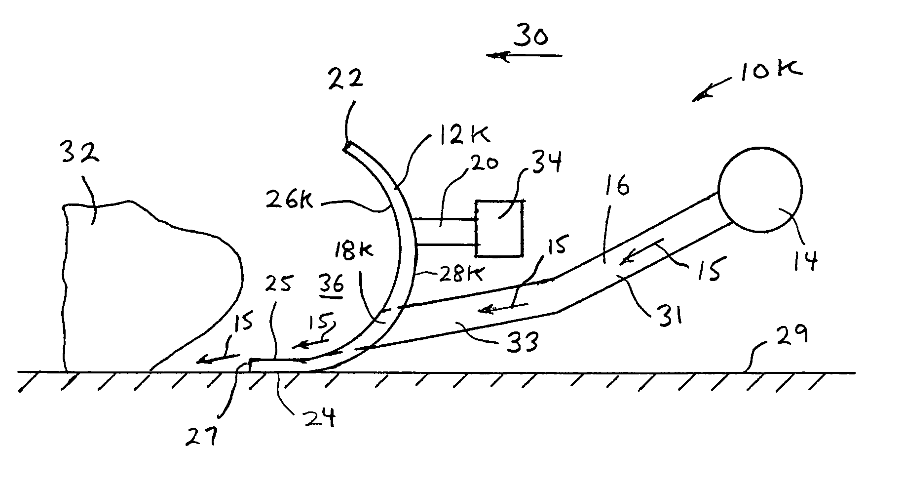
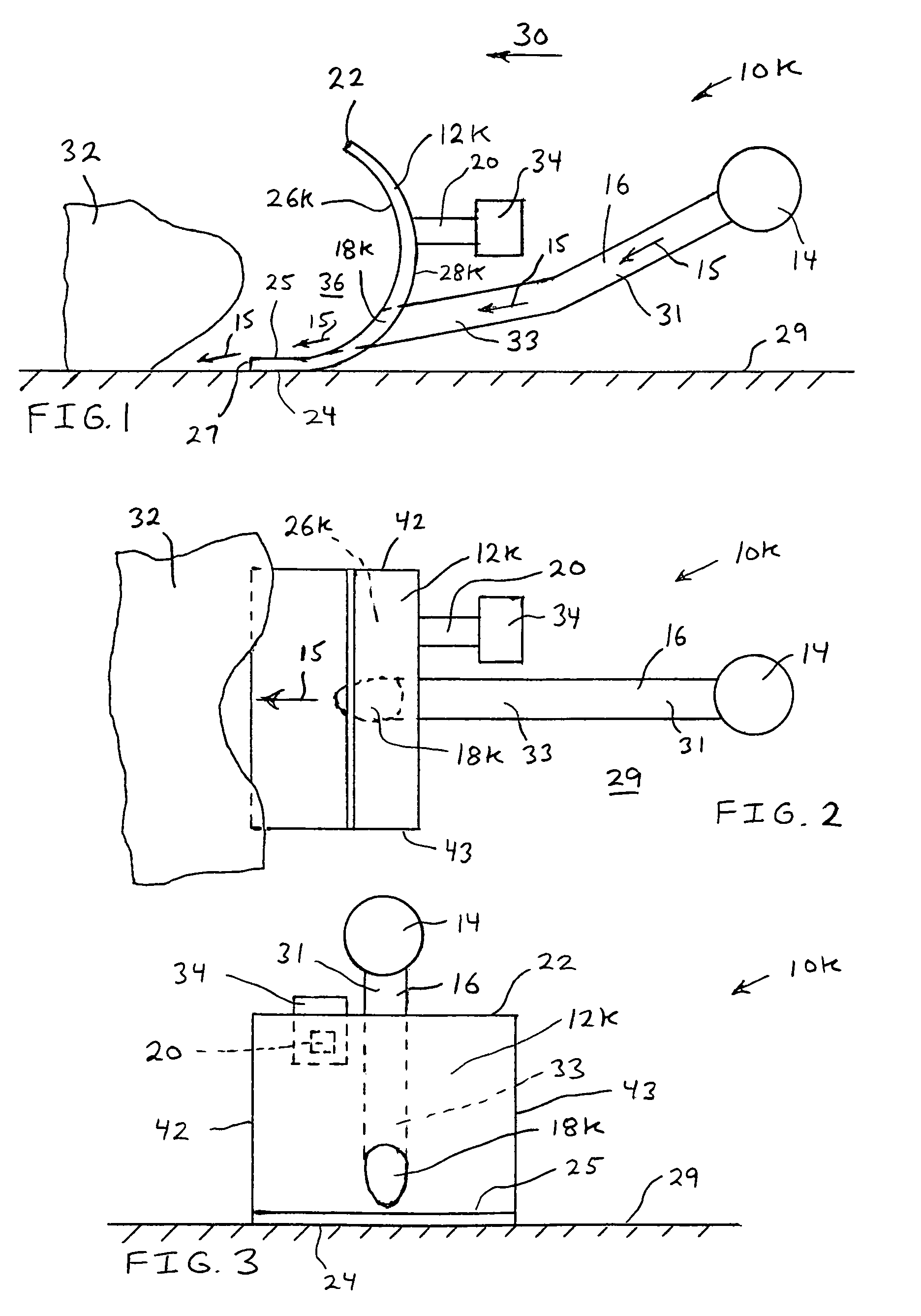
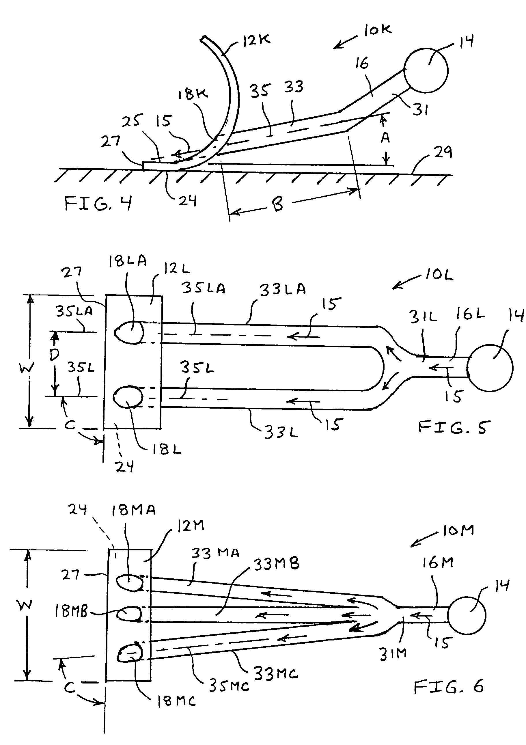
"The present invention provides a fluid shovel apparatus that uses pressurized fluid to easily push and lift loose material such as snow, leaves, sand, dirt, grass clippings, mulch, grain, flour, or any other suitable material. The apparatus has a blade with at least one fluid exhaust port, which allows the pressurized fluid to flow through the blade and eject out through the port, pushing the loose material away from the blade and carrying it in an upward direction. This results in an elimination of friction between the material and the blade, requiring less energy and effort to push the loose material. The apparatus may also include a brush assembly and an ice scraper blade to assist in removing material from a surface of a motor vehicle, as well as a fire suppressant pressurized fluid for use on burning material. The apparatus may also be attached to a train and used to clear snow from train rails."

Problems solved by technology

This lifting requires significant energy for heavy loose material.
Significant work and effort is required to overcome this frictional force.
If the loose material is wet such as snow, wet leaves, wet dirt, or the like, the scraping of the shovel along a support surface does not completely remove the loose material from the support surface.
Additionally, the shovel does not remove any remaining moisture from the support surface.

Method used


Image

  • Fluid shovel apparatus and method
  • Fluid shovel apparatus and method
  • Fluid shovel apparatus and method

Examples


Embodiment Construction

[0033]Although certain preferred embodiments of the present invention will be shown and described in detail, it should be understood that various changes and modifications may be made without departing from the scope of the appended claims. The scope of the present invention will in no way be limited to the number of constituting components, the materials thereof, the shapes thereof, the relative arrangement thereof, etc., and are disclosed simply as an example of the preferred embodiment. The features and advantages of the present invention are illustrated in detail in the accompanying drawings, wherein like reference numerals refer to like elements throughout the drawings. Although the drawings are intended to illustrate the present invention, the drawings are not necessarily drawn to scale.

[0034]Referring to FIG. 1, there is illustrated a side view of a fluid shovel apparatus 10K in accordance with a preferred embodiment of the present invention. The fluid shovel apparatus 10K in...


PUM


Abstract

A fluid shovel apparatus that pushes and lifts loose material such as snow, leaves, sand, dirt, grass clippings, mulch, or the like. The present invention includes at least one fluid exhaust port extending through a blade. Pressurized fluid is ejected through the at least one fluid exhaust port extending through the blade and ejects towards loose material. The loose material floats on a cushion of pressurized fluid that forms between the blade and the loose material. The loose material is pushed away from the blade and is lifted in an upward direction. Additionally, the fluid shovel apparatus may further include a soft pad and an ice scraper blade to assist in removing material from a surface of a motor vehicle. Additionally, the fluid shovel apparatus may be used to deliver a fire suppressant pressurized fluid upon a material that is burning. Additionally, the fluid shovel apparatus may be used to clear snow from railroad train tracks ahead of a railroad train car.

Description

[0001]The present patent application is a continuation-in-part of copending U.S. patent application Ser. No. 12 / 069,139, filed Feb. 7, 2008, and entitled “Fluid Shovel Apparatus and Method,” which is a continuation-in-part of copending U.S. patent application Ser. No. 11 / 786,233, filed Apr. 11, 2007 and entitled “Fluid Shovel Apparatus and Method.” This invention relates generally to shovels for pushing and lifting loose material such as snow, leaves, sand, dirt, grass clippings, mulch, grain, flour, coal, ash, gravel, etc.BACKGROUND OF THE INVENTION[0002]Shovels are well known in the art. Typically, shovels have included a blade that comes in direct contact with loose material while pushing the loose material. Additionally, the loose material must also be lifted and tossed to a desired location. This lifting requires significant energy for heavy loose material. Significant frictional force is created between the blade and the loose material as the loose material is pushed or lifted...

Claims


Application Information

Patent Timeline
Patent Type & Authority Patents(United States)
IPC IPC(8): E01H5/00
CPCA01G1/125E01H1/0818E01H1/101E01H5/02E01H5/076E02F3/02E02F3/8891E02F3/9206A01G20/47
Inventor NAGAMATSU, BRIAN H.NAGAMATSU, FELICIA M.
Owner NAGAMATSU BRIAN H
Learn More