
Shifting device for the mechanical coupling-free transmission of shift commands to the automatic transmission of a motor vehicle

a technology of automatic transmission and shifting device, which is applied in the direction of mechanical control device, manual control with single controlling member, instruments, etc., can solve the problems of inability to actuate the emergency unlocking correspondingly complicated and expensive, and the auxiliary energy is always necessary to disengage the parking brake, etc., to achieve the effect of reliable engagement and disengagement of the parking brak

Inactive Publication Date: 2008-01-29
ZF FRIEDRICHSHAFEN AG
View PDF15 Cites 21 Cited by
  • Summary
  • Abstract
  • Description
  • Claims
  • Application Information

AI Technical Summary

Benefits of technology

The present invention provides a shifting device for an automatic transmission of a vehicle that allows for reliable engagement and disengagement of the parking brake without causing any disturbances to the friction in the mechanical coupling. The shifting device includes a housing and a selector lever that can be moved manually into different positions. The selection of a position engages or disengages the parking brake, and the movement of the selector lever is simple and comfortable during shifting. The shifting device is designed to improve safety and comfort while driving.

Problems solved by technology

The drawback of such solutions with spring-loaded mechanism is that auxiliary energy is always necessary to disengage the parking brake.
Making such an emergency unlocking is correspondingly complicated and expensive.
Another drawback of such a solution with spring-loaded mechanism is that the engagement of the parking brake cannot be triggered under all circumstances by means of the selector lever.
The friction generated during the unnecessary movement of the cable has an adverse effect on the feeling of shifting during shifting in the non-P positions.

Method used


Image

  • Shifting device for the mechanical coupling-free transmission of shift commands to the automatic transmission of a motor vehicle
  • Shifting device for the mechanical coupling-free transmission of shift commands to the automatic transmission of a motor vehicle
  • Shifting device for the mechanical coupling-free transmission of shift commands to the automatic transmission of a motor vehicle

Examples


Embodiment Construction

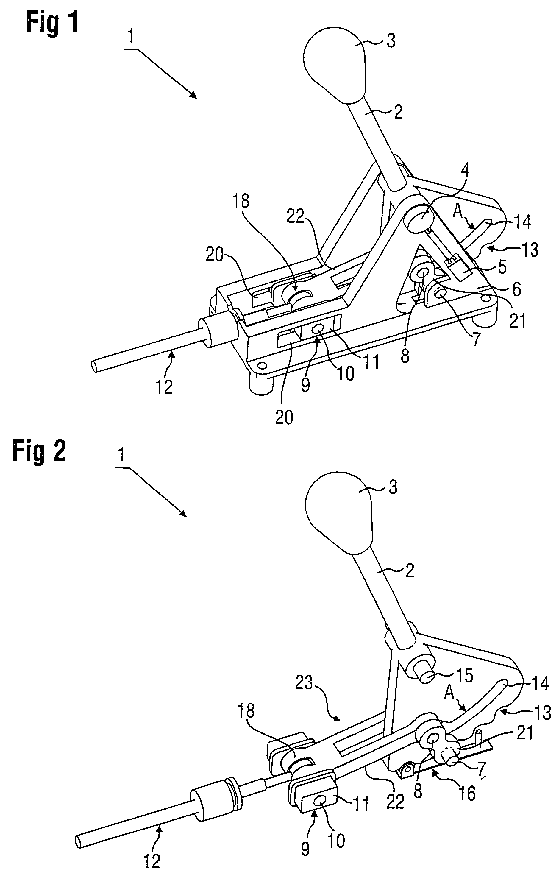
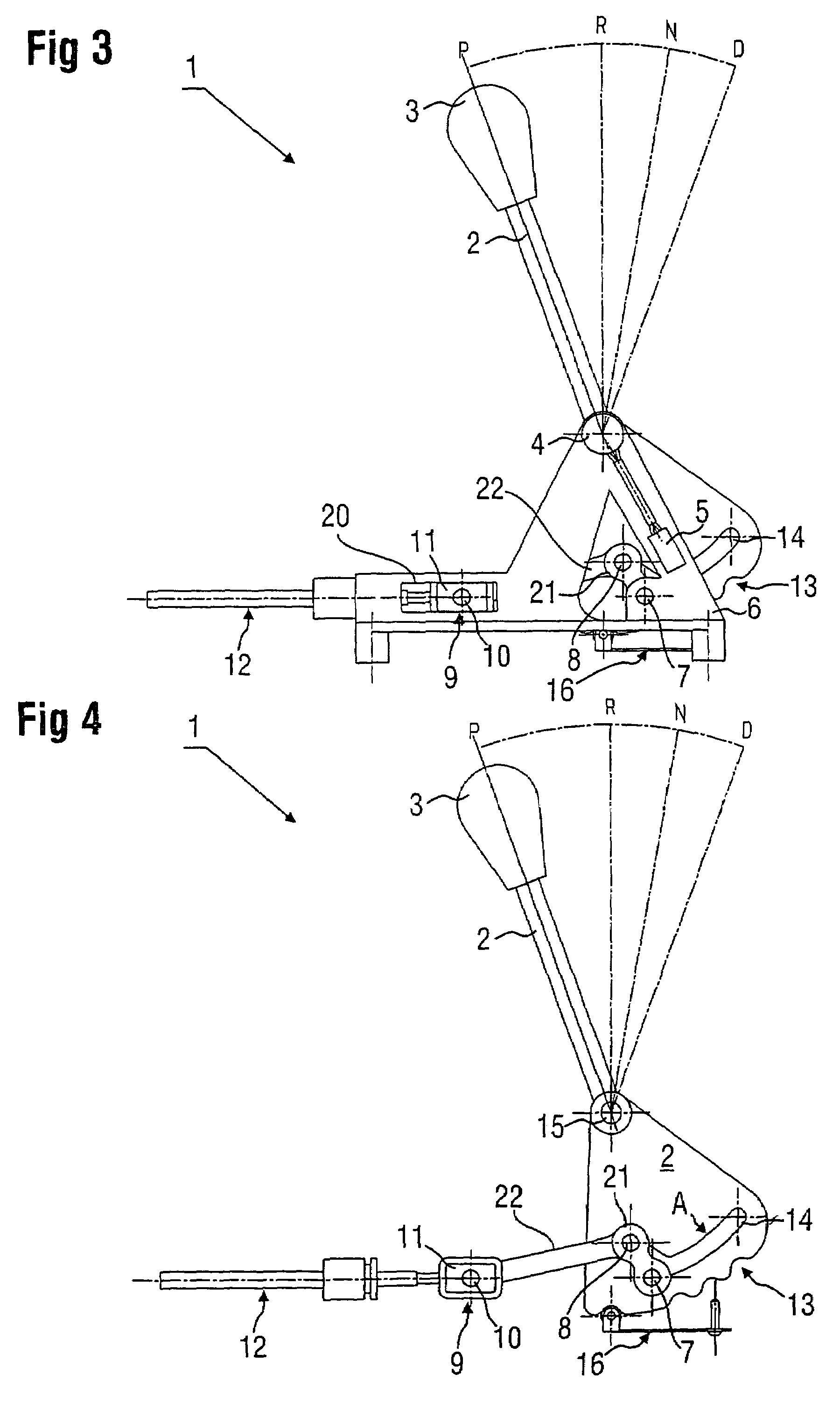
[0058]Referring to the drawings in particular, FIGS. 1 through 13 show a preferred embodiment of the shifting device according to the present invention in different views and detail views for different shift positions of the selector lever.

[0059]FIGS. 1 through 5 show the shifting device 1 with the selector lever position “P.”FIGS. 6 through 9 show the selector lever position “R” and FIGS. 10 through 13 show the selector lever position “D.”

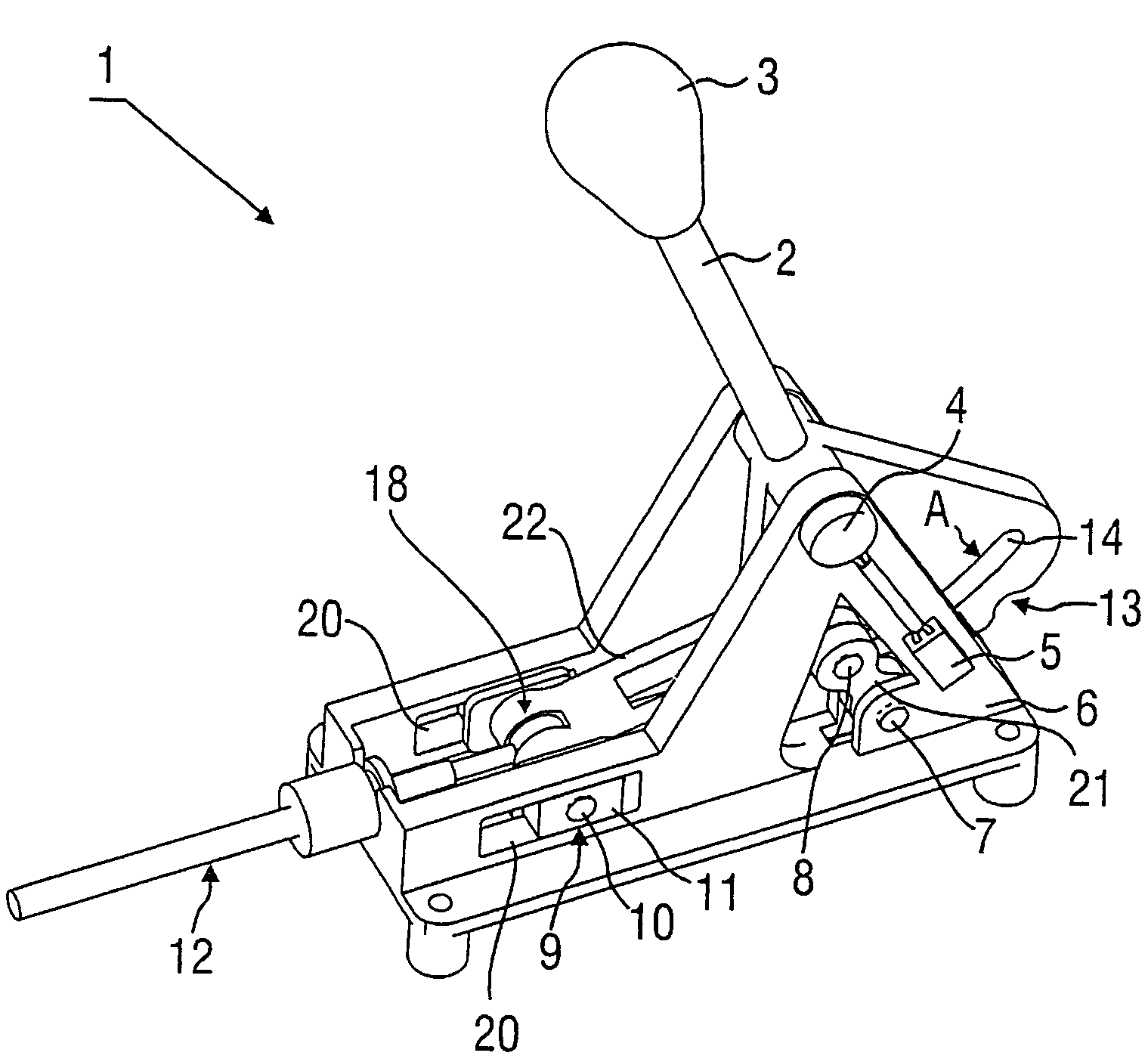
[0060]The complete shifting device according to this embodiment of the present invention can be best recognized from the 3D oblique view. It shows the shifting device 1 with a selector lever 2, which is mounted pivotably about a shift axis 15 and has a knob 3 at the upper part of the selector lever, while the lower side of the selector lever is guided flatly and approximately as a circle sector in the plane of movement. The lower circle sector of the selector lever 2 has a shifting gate slot 14 and a cam 13 located on the edge side for simulating ...


PUM


Abstract

A shifting device (1) for the mechanical coupling-free transmission of shift commands to an automatic transmission of a motor vehicle (shift-by-wire shifting), with at least one housing and / or one frame and one selector lever for the manual selection of shift commands for the vehicle transmission in at least one shift gate. The selector lever can be moved manually into at least four positions (P, R, N, D), pivotable about at least one shift axis. A transmission device(s) transmits the shift commands without mechanical coupling with the vehicle transmission (shift by wire). A mechanical coupling (16) is provided between the selector lever (2) and the transmission of the vehicle. This mechanical coupling (16) activates the parking brake exclusively and automatically when the selector lever (2) is engaged in the P position and is automatically uncoupled from the selector lever when the selector lever (2) is pivoted out beyond the adjacent position.

Description

CROSS REFERENCE TO RELATED APPLICATION[0001]This is a Continuation of and claims the benefit (35 U.S.C. § 120 and 365(c)) of copending International Application PCT / DE2004 / 001144 of Jun. 4, 2004, which designated inter alia the United States and which claims the priority of German Application DE 103 26 118.4 of Jun. 6, 2003, and the entire contents of each application is hereby incorporated by reference in its entirety.FIELD OF THE INVENTION[0002]The present invention pertains to a shifting device for the mechanical coupling-free transmission of shift commands to the automatic transmission of a motor vehicle, i.e., a so-called shift-by-wire shifting device, with at least one housing and / or a frame, a selector lever for the manual selection of shift commands for the transmission of the motor vehicle in at least one shift gate, wherein the selector lever can be moved manually into at least four positions (P, R, N, D), pivotable about at least one shift axis, with transmission devices ...

Claims


Application Information

Patent Timeline
Patent Type & Authority Patents(United States)
IPC IPC(8): B60W10/18F16H59/10F16H63/48
CPCF16H59/105F16H59/0204F16H63/48Y10T74/20043Y10T74/2011Y10T74/20159Y10T74/20073Y10T74/2003Y10T74/2014Y10T74/20067Y10T477/649B60K20/02
Inventor GIEFER, ANDREASMEYER, JORG
Owner ZF FRIEDRICHSHAFEN AG
Learn More