
System to test electronic part and method of controlling the same

a technology of electronic parts and systems, applied in the direction of reradiation, association of printed circuit non-printed electric components, instruments, etc., can solve the problems of increasing the complexity of the system, affecting so as to improve the structure, increase the efficiency of the system, and efficiently test the electronic part

Inactive Publication Date: 2010-10-26
SAMSUNG ELECTRONICS CO LTD
View PDF4 Cites 0 Cited by
  • Summary
  • Abstract
  • Description
  • Claims
  • Application Information

AI Technical Summary

Benefits of technology

[0012]Therefore, it is an aspect of the embodiment to provide a system to test an electronic part having an improved structure and a method of controlling the same, which are capable of automatically detecting the position of a socket according to a variation in position of the socket to efficiently test the electronic part and increasing the efficiency of the system.

Problems solved by technology

However, since the main board, which is a major component of the work box to test the memory chip, should be changed to a new model over time, serious problems may occur at the time of the automation of the system.
This problem may occur when the main board is repaired and mounted again as well as when the main board is replaced with a new board.
Accordingly, it takes a great deal of time to newly change and input the insertion position of the memory chip into the robot.

Method used


Image

  • System to test electronic part and method of controlling the same
  • System to test electronic part and method of controlling the same
  • System to test electronic part and method of controlling the same

Examples


Embodiment Construction

[0033]Reference will now be made in detail to the embodiment, examples of which are illustrated in the accompanying drawings, wherein like reference numerals refer to the like elements throughout. The embodiment is described below to explain the present invention by referring to the figures.

[0034]First, FIG. 3 is a block diagram showing a system to test an electronic part according to an embodiment. The system 100 to test the electronic part includes a distance measuring unit 110, a position measuring unit 120 and a controller 130.

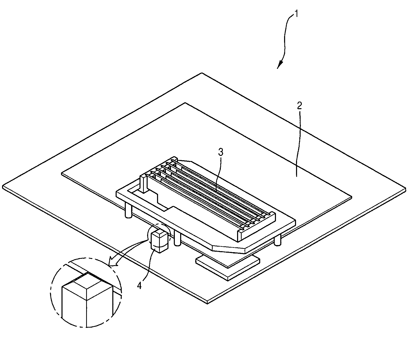
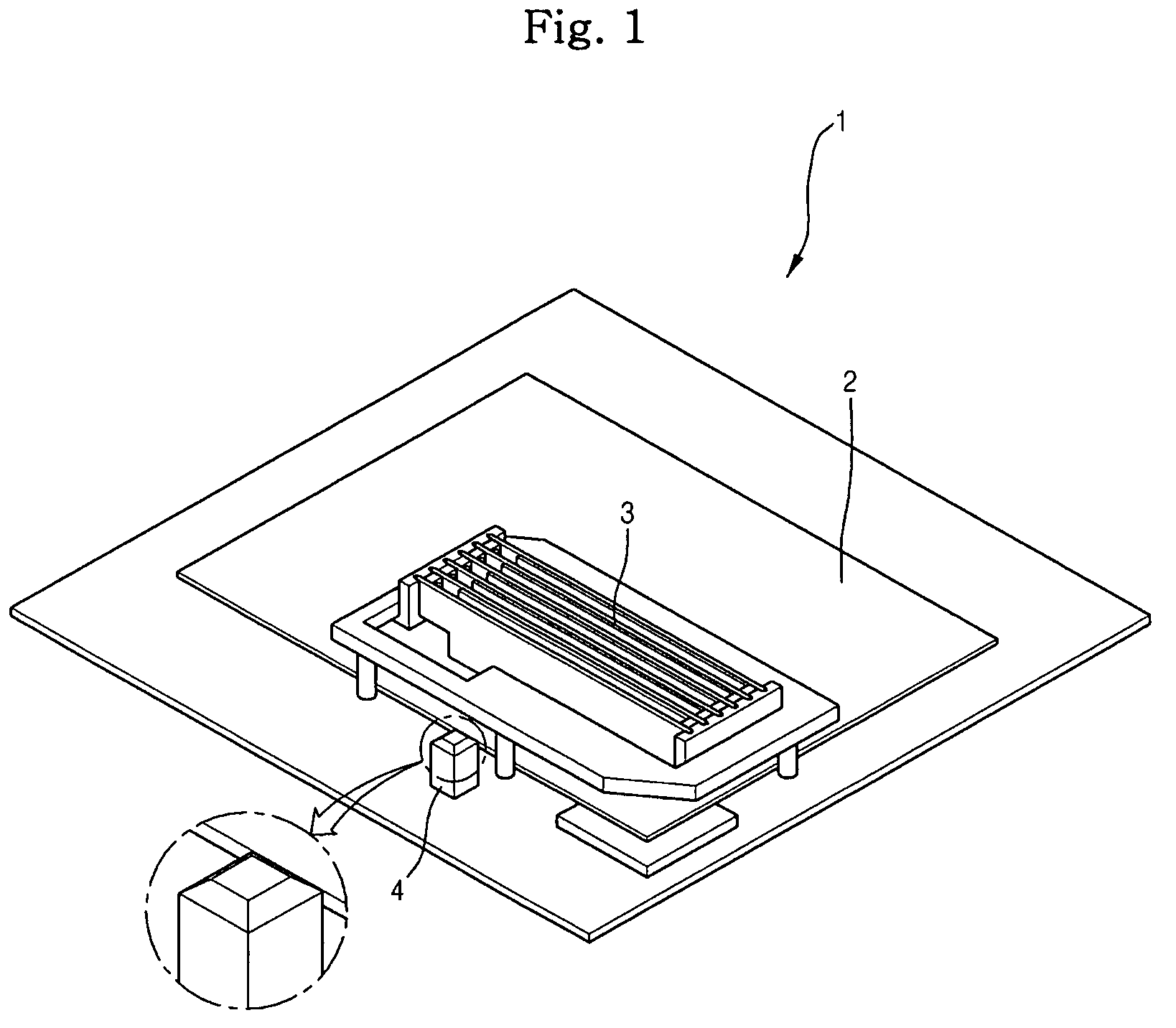
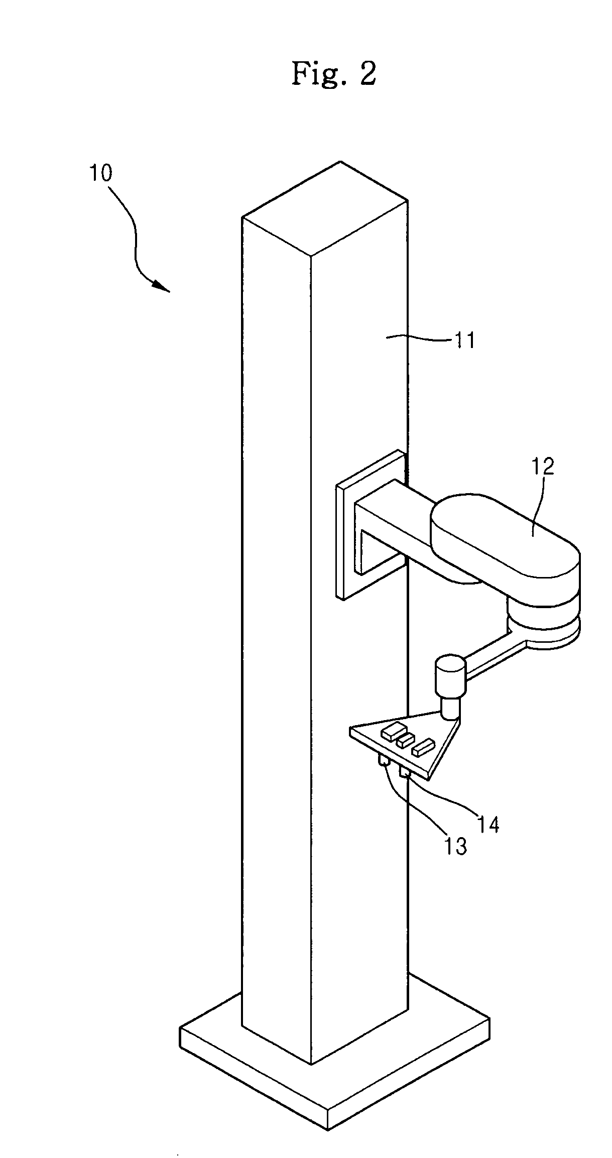
[0035]The system 100 to test the electronic part includes a work box 1 and a robot 10 in order to test the electronic part, as shown in FIGS. 1 and 2.

[0036]The work box 1 is a structure in which a substrate 2 to test the electronic part is mounted and is attached / detached to / from the system. A power supply for a personal computer (PC) and a hard disc are provided in the work box such that the work box performs a function similar to that of a general PC.

[00...


PUM

PropertyMeasurementUnit
distance measuringaaaaaaaaaa
distanceaaaaaaaaaa
sizeaaaaaaaaaa

Abstract

Disclosed herein are a system to test an electronic part and a method of controlling the same, which are capable of automatically detecting a position of a socket according to a variation in a position of the socket to efficiently test the electronic part. The system to test an electronic part using a robot to automatically test the electronic part includes: a distance measuring unit measuring a distance between a socket mounted on a substrate to test the electronic part and a reference block to provide a reference position; a position measuring unit detecting positional information of the reference block; and a controller calculating positional information of the socket using the measured distance between the socket and the reference block on the basis of the detected positional information of the reference block and controlling the robot using the calculated positional information of the socket.

Description

CROSS-REFERENCE TO RELATED APPLICATIONS[0001]This application claims the benefit of Korean Patent Application No. 2007-30780, filed on Mar. 29, 2007 in the Korean Intellectual Property Office, the disclosure of which is incorporated herein by reference.BACKGROUND[0002]1. Field[0003]The present invention relates to a system to testing an electronic part, and, more particularly, to a system to testing an electronic part and a method of controlling the same, which are capable of automatically detecting a position of a socket according to a variation in position of the socket so as to test the electronic part.[0004]2. Description of the Related Art[0005]Recently, as semiconductor technology has been rapidly developed, the small size and high density of all electrical / electronic apparatuses have been realized. In addition, as industrial robots have been developed, test devices to test the capabilities of the electrical / electronic apparatuses using the robots have been developed.[0006]For...

Claims


Application Information

Patent Timeline
Patent Type & Authority Patents(United States)
IPC IPC(8): G01N21/86G01R31/26H05K1/00
CPCG01R31/2891G01S17/02G01S17/875H05K1/18
Inventor KIM, SEONOYONG, HYUNG JUNGPARK, CHUL JUN
Owner SAMSUNG ELECTRONICS CO LTD
Learn More