
Surface communication apparatus and method for use with drill string telemetry

a communication apparatus and telemetry technology, applied in the field of drilling and producing hydrocarbon wells, can solve the problems that the manner in which this can be advantageously achieved has not yet been realized

Active Publication Date: 2010-10-19
INTELLISERV LLC
View PDF6 Cites 109 Cited by
  • Summary
  • Abstract
  • Description
  • Claims
  • Application Information

AI Technical Summary

Problems solved by technology

However, the manner in which this can be advantageously achieved has not heretofore been realized.

Method used


Image

  • Surface communication apparatus and method for use with drill string telemetry
  • Surface communication apparatus and method for use with drill string telemetry
  • Surface communication apparatus and method for use with drill string telemetry

Examples


Embodiment Construction

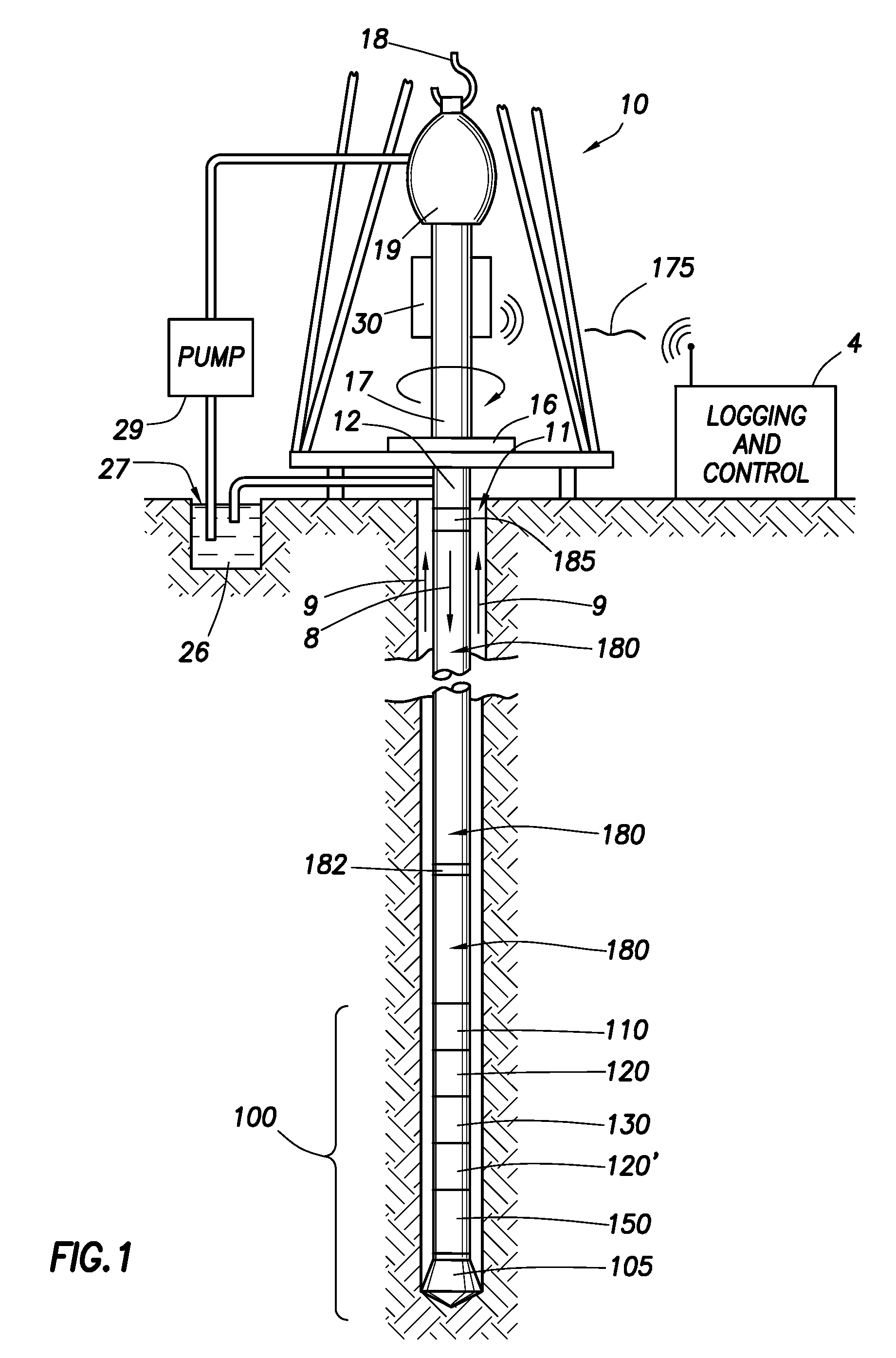
[0029]FIG. 1 illustrates a wellsite system in which the present invention can be employed. The wellsite can be onshore or offshore. In this exemplary system, a borehole 11 is formed in subsurface formations by rotary drilling in a manner that is well known. The drilling could alternatively be mud-motor based directional drilling, as is also well known.

[0030]A drill string 12 is suspended within the borehole 11 and has a bottom hole assembly 100 which includes a drill bit 105 at its lower end. The surface system includes platform and derrick assembly 10 positioned over the borehole 11, the assembly 10 including a rotary table 16, kelly 17, hook 18 and rotary swivel 19. The drill string 12 is rotated by the rotary table 16, energized by means not shown, which engages the kelly 17 at the upper end of the drill string. The drill string 12 is suspended from a hook 18, attached to a traveling block (also not shown), through the kelly 17 and a rotary swivel 19 which permits rotation of the...


PUM


Abstract

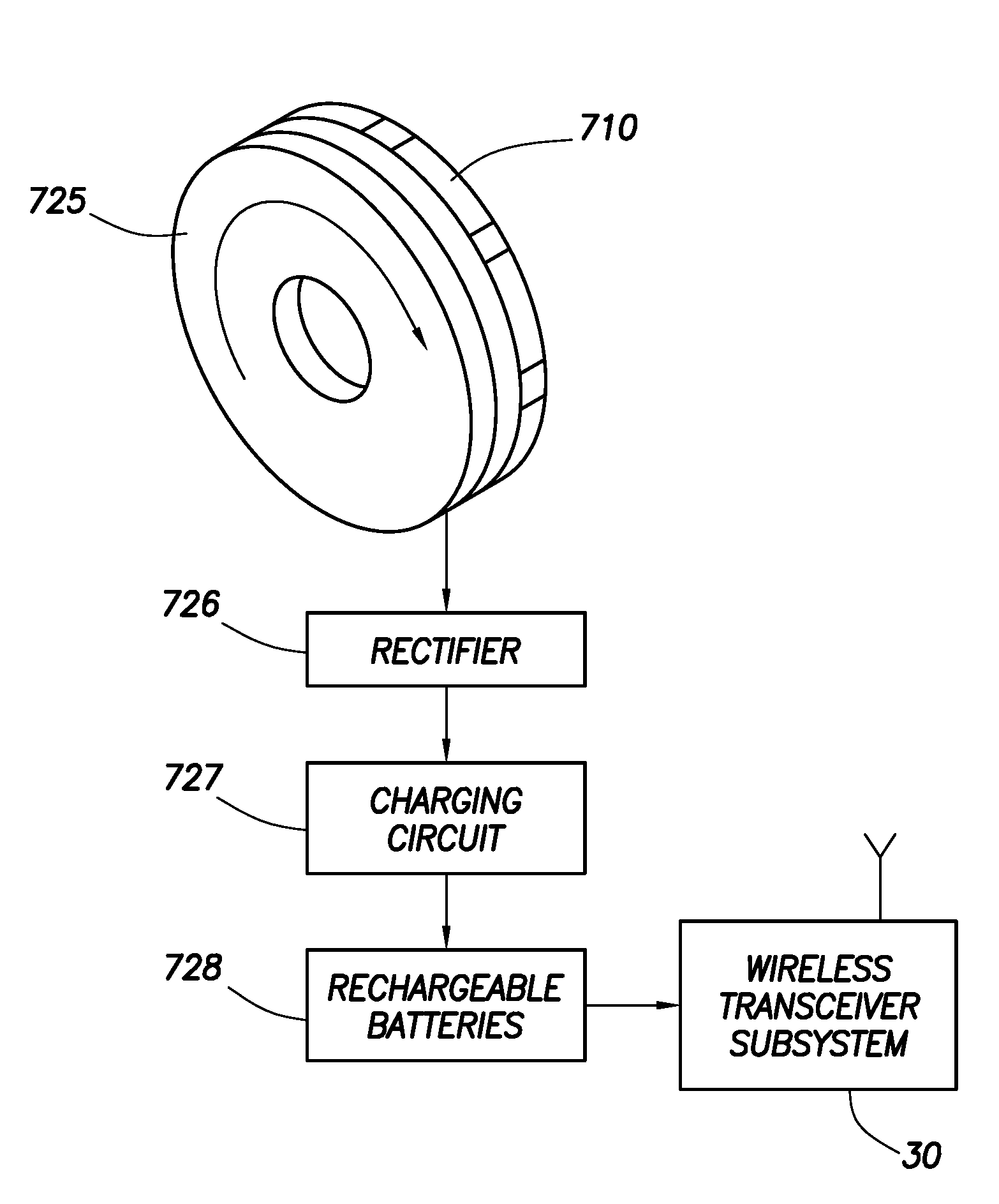
An operation of drilling an earth borehole uses a drilling rig, a drill string of drill pipes having its generally upper end mechanically coupleable with and suspendable from the drilling rig, a drive string portion of the drill string, mechanically coupleable with the topmost drill pipe of said drill string, and a drive mechanism mechanically coupleable with the drive string for rotating the drive string and the drill string. A system for generating electric power in the region of the drive string includes an electric generator, which includes a rotating generator component mounted on said drive string for rotation therewith and a stationary generator component mounted on a stationary portion of the drilling rig. The rotating generator component produces electric power in the region of the drive string.

Description

CROSS-REFERENCE TO RELATED APPLICATIONS[0001]The present Application is a divisional of U.S. application Ser. No. 11 / 498,847 filed Aug. 3, 2006, and claims priority from U.S. Provisional Patent Application No. 60 / 705,326, filed Aug. 4, 2005, and also claims priority from U.S. Provisional Patent Application No. 60 / 708,561, filed Aug. 16, 2005, and both said U.S. Provisional Patent Applications are incorporated herein by reference. The present Application contains subject matter that relates to subject matter disclosed in copending U.S. patent application Ser. Nos. 11 / 498,845, titled “Bidirectional Drill String Telemetry for Measuring and Drilling Control,” (hereinafter “the '845 Application”) and 11 / 995,027, titled “Interface and Method for Wellbore Telemetry System” (hereinafter “the '027 Application”), both filed on Aug. 3, 2006 of even date herewith, and both assigned to the same assignee as the present Application.STATEMENT REGARDING FEDERALLY SPONSORED RESEARCH OR DEVELOPMENT[00...

Claims


Application Information

Patent Timeline
Patent Type & Authority Patents(United States)
IPC IPC(8): G01V3/00
CPCE21B17/003E21B17/028E21B47/12E21B47/122G01V11/002E21B47/13
Inventor LI, QIMINGSANTOSO, DAVIDSHERMAN, MARKMADHAVAN, RAGHULEBLANC, RANDALL P.THOMAS, JOHN A.MONTERO, JOSEPH
Owner INTELLISERV LLC
Learn More