
Reinforcing member for vehicle center pillar

a technology for reinforcing members and vehicle centers, which is applied in the direction of roofs, transportation and packaging, vehicle arrangements, etc., can solve the problems of difficult pressing for securing the predetermined shape accuracy in the reinforcing member, reducing the balance of strength, and reducing the accuracy of predetermined shape accuracy. , to achieve the effect of suppressing the increase of weight, reducing the balance of strength, and easy and inexpensive pressur

Active Publication Date: 2010-10-19
TOYODA IRON WORKS CO LTD
View PDF16 Cites 23 Cited by
  • Summary
  • Abstract
  • Description
  • Claims
  • Application Information

AI Technical Summary

Benefits of technology

[0012]The present invention has been made with the above circumstances as a background, and has objects to manufacture a reinforcing member having a predetermined shape accuracy easily and inexpensively by pressing i.e. press-working, by (i) securing a predetermined safety performance while suppressing increase of weight and lowering of balance of strength and rigidity of a reinforcing member as a whole; (ii) suppressing deformation by camber recovery and twisting due to non-uniform residual stress regardless of employment of a high tensile steel plate; and (iii) improving press forming properties of a roof side T-shaped portion to suppress generation of cracks and burrs.

Problems solved by technology

However, with the center pillar reinforcing member constructed by the two members i.e. the upper member and the lower member that are different in tensile strength as in Patent Document 1, non-uniform residual stress is generated readily in a product interior at the upper part constructed by the ultra-high tensile steel plate.
Thus, deforming amounts due to camber recovery that accompanies elastic recovery and twisting become large, which lowers shape accuracy (see FIG. 3).
This makes pressing for securing the predetermined shape accuracy in the reinforcing member difficult.
Also, at a roof side T-shaped portion of the reinforcing member i.e. at an upper T-shaped portion connected to a roof side rail, defects such as cracking occur readily in a product cross-section, due to poor pressing forming property such as drawing property.
Moreover, because of inclination of the upper part of the reinforcing member toward an inner side of the vehicle, an angle thereof changes compared with a general pressing direction, so that the door frame corner portions being difficult in the outer trimming tend to generate burr readily.
Lowered yield and productivity due to generation of such cracks and burrs, the employment of expensive ultra-high tensile steel, and the abovementioned difficulty of pressing, cause a large increase of manufacturing cost.
Moreover, strength and rigidity of the upper reinforcing member resulted from the small section modulus and thin plate thickness are relatively lowered, which worsens balance of strength and rigidity of the reinforcing member as a whole.
For this reason, an adequate safety performance increasing effect of the reinforcing member cannot be obtained necessarily.

Method used


Image

  • Reinforcing member for vehicle center pillar
  • Reinforcing member for vehicle center pillar
  • Reinforcing member for vehicle center pillar

Examples


Embodiment Construction

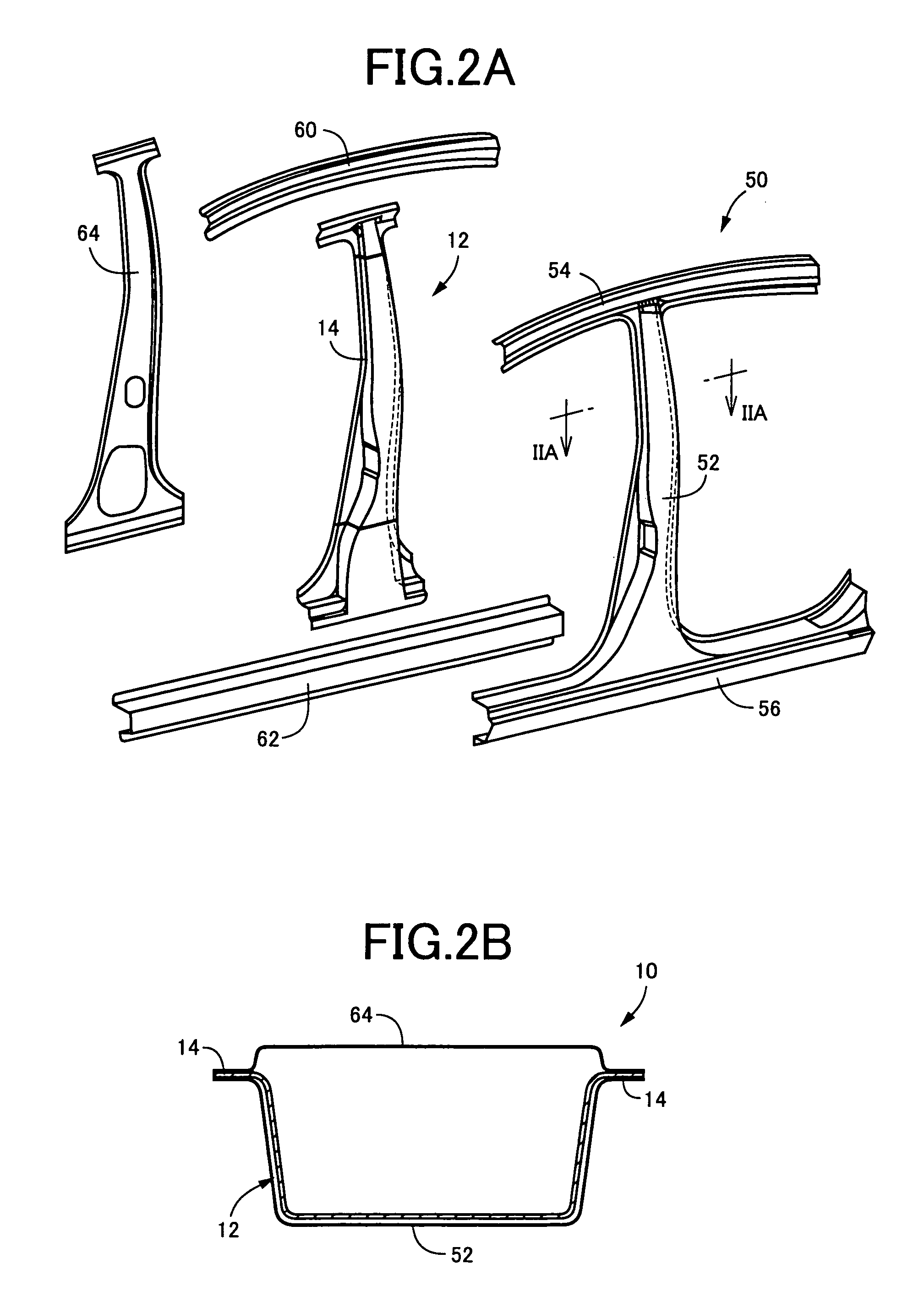
[0027]The reinforcing member according to the present invention is integrally fixed by fixing means such as welding and bolt fastening to an inside of a center pillar constructed by a center pillar outer panel and a center pillar inner panel to have a closed cross section. However, the shape and structure of the center pillar itself can be determined as suited, and the center pillar does not necessarily have the closed cross section, for example.

[0028]The plurality of steel plates constructing the reinforcing member, specifically, the three steel plates different in tensile strength, are integrally bonded by welding such as an arc welding, seam welding, plasma welding, laser welding, or spot welding, for example. The welding is performed with lateral ends being butted against each other within the same plane, or with the lateral ends being overlapped by just predetermined dimensions. Plurality of steel plates are formed to a predetermined shape thereafter by cold pressing or hot pre...


PUM


Abstract

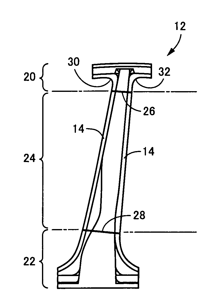
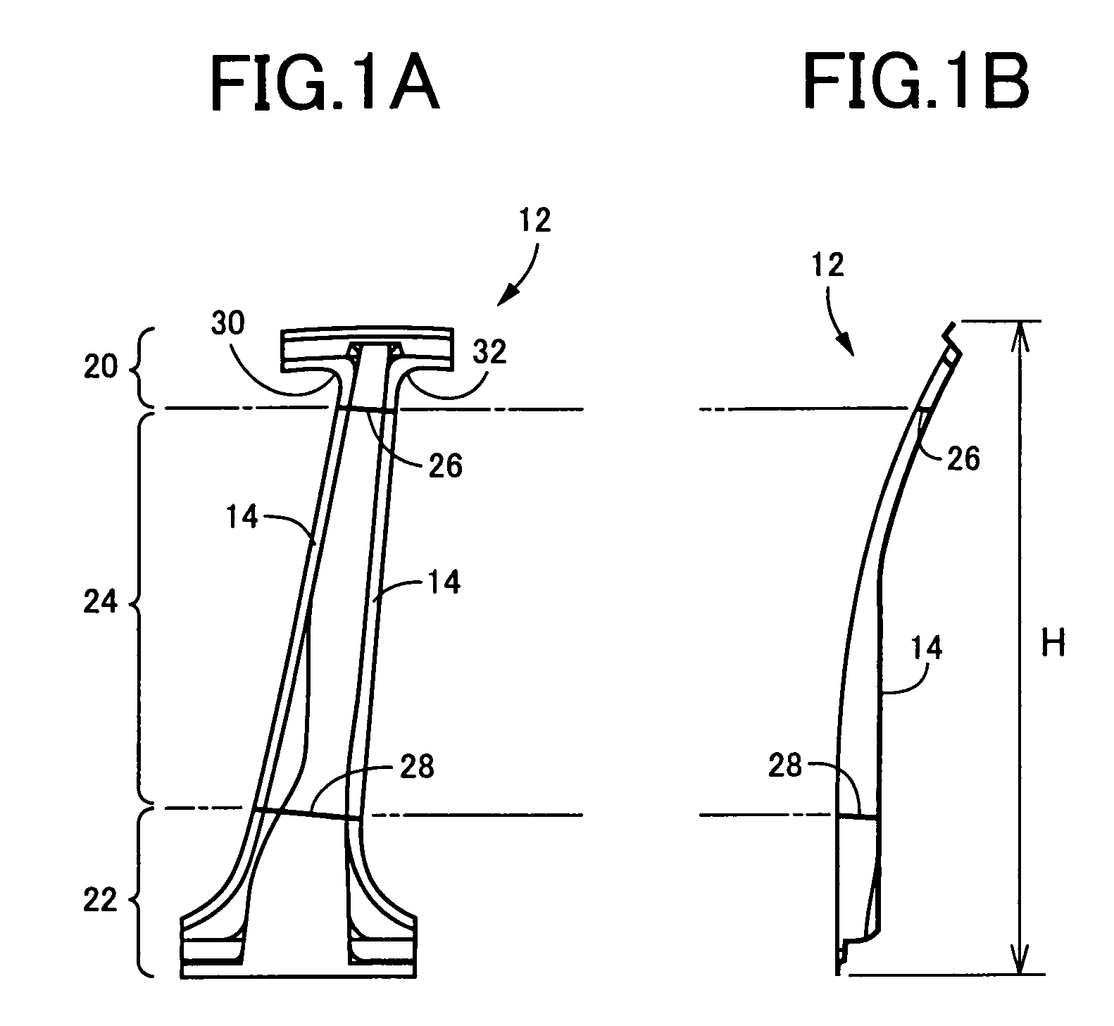
Deformation by camber recovery etc. due to non-uniform residual stress is suppressed, and occurrence of crack and burr is suppressed by improving press forming property of a roof side T-shaped portion, so that a reinforcing member having a predetermined shape accuracy is manufactured easily and inexpensively by pressing. A reinforcing member (12) is constructed by three members, i.e. an upper member (20), a lower member (22) and a central member (24). A tensile strength of the upper member (20) is selected lower than that of the central member (24), and is higher than that of the lower member (22). In comparison to a case where the upper member (20) and the central member (24) are constructed integrally by an ultra-high tensile steel plate, fluctuation of internally generated residual stress is made small. Shape accuracy is thereby improved by the reduced deforming amount due to camber recovery etc., thus press forming being facilitated. Also, a roof side T-shaped portion constructed by the upper member (20) is improved in the drawing property, and the door frame corner portions (30) and (32) are improved in the outer trimming property. Thus, the shape accuracy is improved, and yield and productivity is increased by suppression of crack generation.

Description

[0001]The present application is based on Japanese Patent Application No. 2007-163105, and content thereof is incorporated herein.BACKGROUND OF THE INVENTION[0002]1. Field of the Invention[0003]The present invention relates to a reinforcing member for vehicle center pillar, and especially it relates to an improvement of a reinforcing member constructed using a plurality of steel plates that are different in tensile strength.[0004]2. Description of the Prior Art[0005]To secure safety in a lateral collision of an automobile, a center pillar is reinforced. That is, a reinforcing member (reinforcement) is fitted and fixed integrally by welding to an interior of a center pillar constructed by a center pillar outer panel and a center pillar inner panel to have a closed cross-section. Due to characteristics of cross-sectional shape, such a center pillar reinforcing member is low in the section modulus (corresponding to a cross section second moment) at an upper part, and is high in the sec...

Claims


Application Information

Patent Timeline
Patent Type & Authority Patents(United States)
IPC IPC(8): B62D25/04B60R99/00
CPCB62D25/04B62D25/025
Inventor OBAYASHI, AKIRA
Owner TOYODA IRON WORKS CO LTD
Learn More