[0026]These and other features and advantages of the present invention will be presented in more detail in the following specification of the invention and the associated figures.
[0027]The present invention may best be understood by reference to the following description taken in conjunction with the accompanying drawings in which:
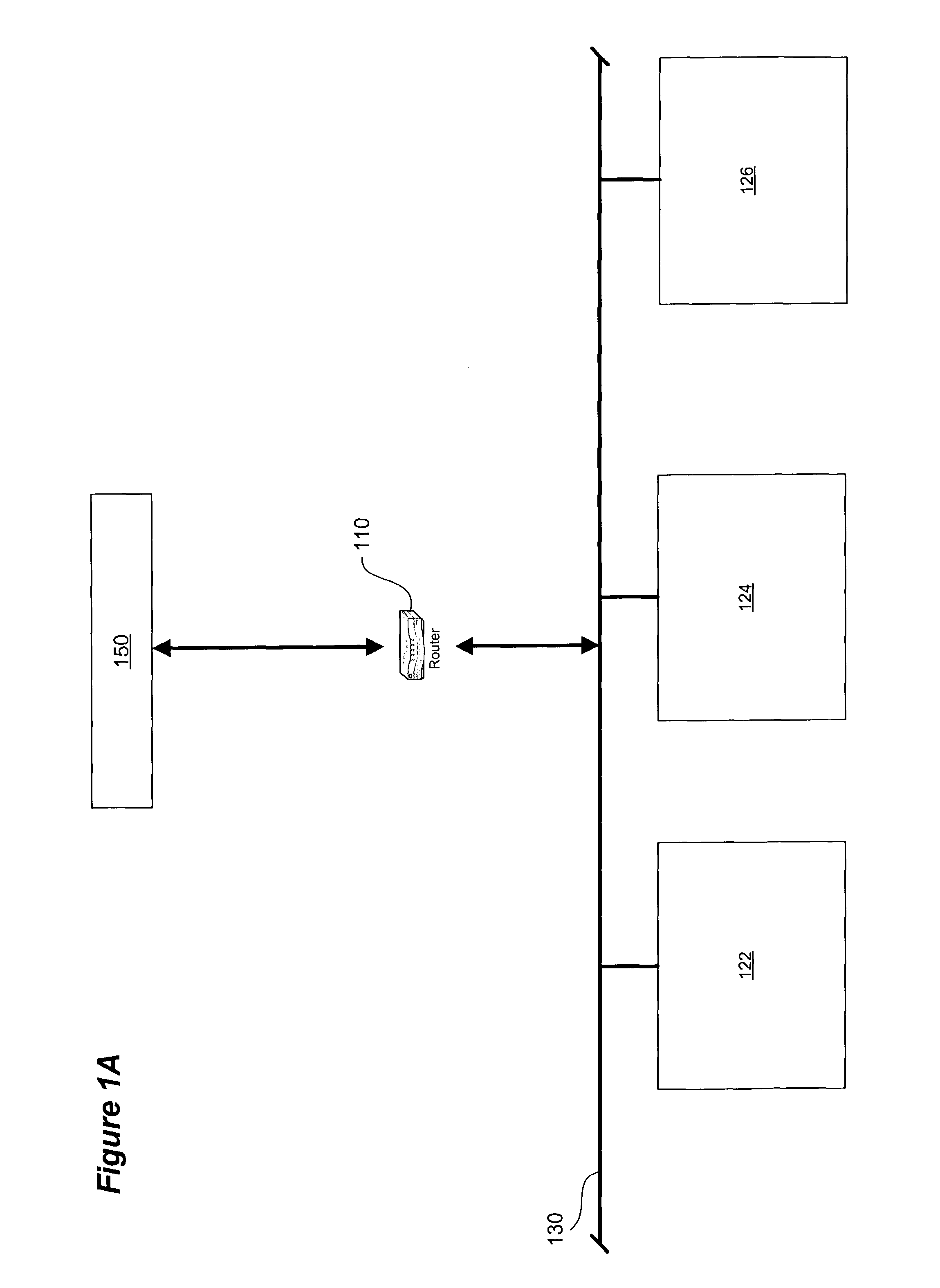
[0028]FIG. 1A is a
schematic diagram of the logical structure a gateway service for hosts in a LAN.
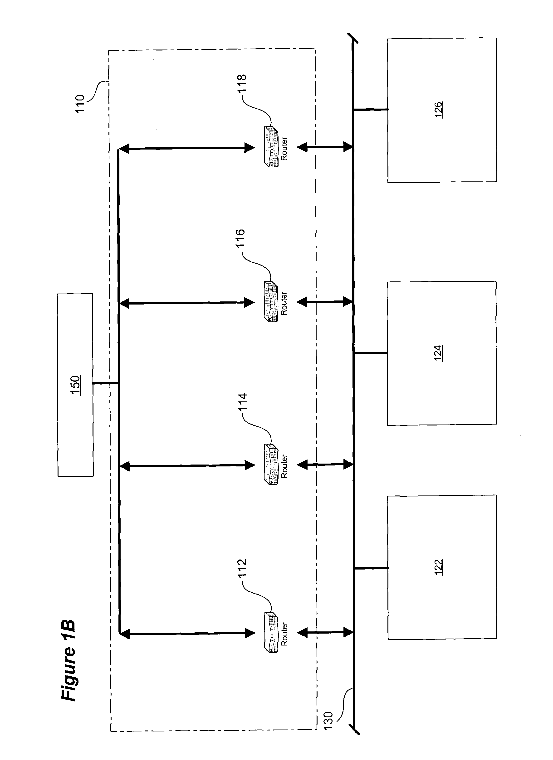
[0029]FIG. 1B is a
schematic diagram of the
physical structure of the gateway service shown in FIG. 1A in which multiple gateway devices are used in a redundancy group to provide resiliency.
[0030]FIG. 2 is a
schematic diagram of a
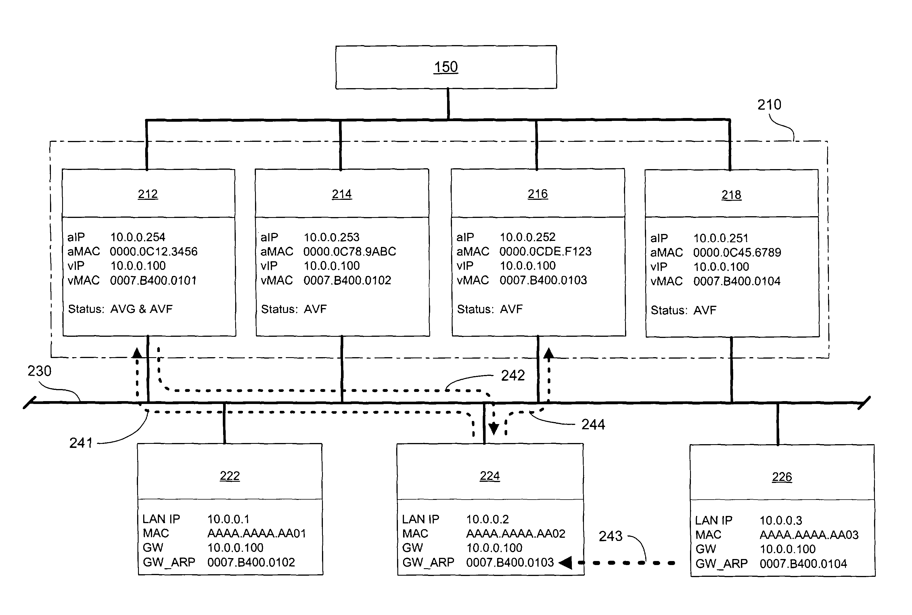
virtual router in which several routers are available to both direct traffic outside the local network and also to provide translation services using a distributed NAT database available to the members of the redundancy group, using the present invention.
[0031]FIG. 3 shows assignment of address blocks to individual gateway devices after partitioning of a
pool of unique IP addresses for use in NAT services.
[0032]FIG. 4 shows translation and updating of the redundancy group according to one embodiment of the present invention.
[0033]FIG. 5 shows failure of a redundancy group member and NAT database availability and re-assignment of the failed gateway device's vMAC address using one embodiment of the present invention.
[0034]FIG. 6 is a diagrammatic representation of a router in which embodiments of the present invention may be implemented.
[0035]Reference will now be made in detail to the preferred embodiment of the invention. An example of the preferred embodiment utilizing products, protocols, methods, systems and other technology developed, sold and / or used by Cisco Systems is illustrated in the accompanying drawings. While the invention will be described in conjunction with that preferred embodiment, it will be understood that it is not intended to limit the invention to one preferred embodiment or to its implementation solely in connection with Cisco products and systems. On the contrary, the following description is intended to cover alternatives, modifications, and equivalents as may be included within the spirit and scope of the invention as defined by the appended claims. In the following description, numerous specific details are set forth in order to provide a thorough understanding of the present invention. The present invention may be practiced without some or all of these specific details. In other instances, well known process operations have not been described in detail in order not to unnecessarily obscure the present invention.
[0036]The following terms are used in the instant specification. Their definitions are provided to assist in understanding the preferred embodiments described herein, but do not necessarily limit the scope of the invention.
[0037]A “host” is a PC, or other arbitrary network entity residing on a LAN, that periodically communicates with network entities outside the LAN on which the host resides through a router or bridge. The term “user” may be used equivalently in this disclosure.
[0038]A “router” is a piece of hardware which operates at the
network layer to direct packets between various LANs or WANs of a network. The
network layer generally allows pairs of entities in a network to communicate with each other by finding a path through a series of connected nodes. Other terms that may be used in this disclosure include layer 3 switch, layer 3 device and gateway or gateway device which are not necessarily the same as a router, but which may function in the same place and manner as a router. Any and all of these terms are intended to be interpreted as broadly as possible, unless specifically defined more narrowly.
[0039]An “IP (
internet protocol) address” is a
network layer address for a device operating in the IP suite of protocols. The
IP address is typically a 32
bit field, at least a portion of which contains information corresponding to its particular
network segment. Thus, the
IP address of a router may change depending upon its location in a network. An
IP address that is referred to as “unique” may be globally unique or may be sufficiently unique for the uses for which it is intended (for example, in a limited network environment in which globally unique IP addresses are unnecessary, but in which local IP addresses used on a local network are not sufficiently unique).
[0040]A “
MAC address” is a
data link layer device address, defined by the IEEE 802 committee that deals with issues specific to a particular type of LAN. The types of LANs for which MAC (an acronym for
Media Access Control) addresses are available include
token ring, FDDI and
Ethernet. A MAC address generally is intended to apply to a specific physical device no matter where it is plugged into the network. Thus, a MAC address generally is hardcoded into the device—on a router's ROM, for example. This should be distinguished from the case of a network layer address, described above, which changes depending upon where it is plugged into the network. Also, a real MAC address (such as a “burned in address” or BIA MAC address) can be distinguished from a “virtual address” (as defined below) which can include a virtual MAC address.
[0041]A “virtual address” is an address, typically (but not necessarily) shared by a group of real network entities, corresponding to a
virtual entity. In the context of this invention, one real router from among two or more real routers emulates a virtual router by adopting the virtual address, and another entity (usually a host) is configured to send data packets to such virtual address, regardless of which real router is currently emulating the virtual router. In the preferred embodiments, the virtual addresses may encompass both MAC layer and network layer (IP) addresses. Usually, various members of the group each have the capability of adopting the virtual address(es) to emulate a
virtual entity.
[0042]A “packet” is a collection of data and control information including source and destination node addresses, formatted for transmission from one node to another. In the context of this invention, it is important to note that hosts on one LAN send packets to hosts on another LAN through a router or bridge connecting the LANs.
[0043]“IP aliases” are the addresses that belong to a device, including the addresses that are configured on the device's interfaces and any addresses not configured on the interfaces, but which are owned by the device.
[0044]The present invention uses a load-sharing
system or protocol in connection with NAT services to permit distributed forwarding of packets that are sent from hosts requiring unique IP addresses and which are subsequently sent across multiple gateway devices acting as one or more virtual gateways for communications outside a local subnet. A distributed NAT database (translation and context information) is maintained in a group of routers that are providing this redundant, load-sharing virtual router service. One or more embodiments of the present invention will be explained using Cisco's GLBP as a non-limiting example of a load-sharing protocol for the redundancy group. Those skilled in the art will appreciate that other similar methods, apparatus, etc. can be used so long as they allow packets destined to a single virtual between or other IP address to be forwarded by multiple actual gateway devices. As used herein, the
phrase “load-sharing redundancy group” means any apparatus, method, etc. that allows packets destined for a single IP address to be forwarded by multiple gateway devices which also work together to provide
failover services in the event of a gateway
device failure.
[0045]In one embodiment of the present invention shown in FIG. 2, the redundancy group is a GLBP group using routers as gateway devices. Each router in the GLBP group is an AVF and is assigned a virtual MAC address. In prior systems, NAT typically has been implemented by an individual address assigning / translation device using a
pool of unique IP addresses that can be temporarily assigned to the non-unique local addresses used by hosts in a LAN. In such prior systems, the assigning device performing translations maps hosts' local addresses to available unique addresses, and also maintains a database of the mappings.
[0046]In the embodiment of the present invention shown in FIG. 2, the AVG 212 maintains the master NAT database. The NAT process in each router can be notified which router in the GLBP group is the AVG for that group using services and / or protocols known to those skilled in the art. When a NAT process learns of a new AVG then it will register with the NAT process in the AVG and will receive a copy of the master NAT database in return. In another embodiment of the present invention, the NAT database is maintained by each gateway device separately, so that each router or other device as its own “copy” of the gateway's NAT mappings.
[0047]As seen in FIG. 2, virtual gateway 210 is made up of multiple actual gateway device routers 212, 214, 216 and 218. Each gateway device has an aIP address, an aMAC address and re-assignable virtual MAC address (also referred to as a vMAC address) assigned to it. All gateway devices in redundancy group 210 share vIP address 10.0.0.100. As illustrated, gateway device 212 uses actual IP address 10.0.0.254, actual MAC address 0000.0C12.3456 and vMAC address 0007.B400.0101; gateway device 216 uses actual IP address 10.0.0.252, actual MAC address 0000.0CDE.F123 and vMAC address 0007.B400.0103. In this embodiment of the present invention, the last 4 digits of the vMAC address identify the redundancy group (for example, 01xx in FIG. 2) and the forwarding gateway device (for example, xx01, xx02, xx03 or xx04 in FIG. 2). Other addressing schemes may be used and such variations will be appreciated by the those skilled in the art after reviewing the present disclosure.
[0048]The hosts on the local subnet which virtual router group 210 serves are hosts 222, 224 and 226. Each host has its own non-unique IP address (which is unique on the subnet) and a MAC address. As with prior GLBP systems, the hosts have been pre-programmed in any suitable manner with the
gateway address of the virtual router group, in this case 10.0.0.100. For example, host 224 has a LAN IP address of 10.0.0.2 and a MAC address of AAAA.AAAA.AA02. The ARP resolution protocol and apparatus is similar to a standard GLBP
system. When a host 224 sends an ARP request, indicated by arrow step 241, to the gateway IP address (for example, 10.0.0.10), the GLBP gateway device 212 sends to the requesting host 224, at step 242, the vMAC address of a gateway device. At step 243, the host 224 caches this vMAC address and then, at step 244, sends packets destined for an outside network outside the LAN to the gateway device 216 then possessing the cached vMAC address (here, 0007.B400.0103).
[0049]As seen in FIG. 3, the entire pool 310 of available globally unique IP addresses (and / or other addresses to be used for translation purposes) is partitioned (for example, by or under the control of the GLBP gateway device) into address blocks 310a, 310b, 310c and 310d. In the example of FIG. 3, 80 unique IP addresses (15.21.21.00 through 15.21.21.79) are available from general
address pool 310 to be used by the redundancy group and its hosts for NAT services. One or more blocks of addresses are assigned to each individual AVF 212, 214, 216 and 218. In the example illustrated in FIG. 3, block 310a (containing addresses 15.21.21.00 through 15.21.21.19) is assigned to gateway device 212, block 310b (containing addresses 15.21.21.20 through 15.21.21.39) is assigned to gateway device 214, block 310c (containing addresses 15.21.21.40 through 15.21.21.59) is assigned to gateway device 216 and block 310d (containing addresses 15.21.21.60 through 15.21.21.79) is assigned to gateway device 218.
[0050]Once the addresses have been allocated, gateway devices can start providing NAT services to hosts on the subnet. Hosts are assigned to AVFs in accordance with a prescribed
algorithm or methodology, which will be discussed in more detail below. In the embodiment of the present invention shown in FIG. 4, host 224, using a methodology such as the one illustrated in FIG. 2, has ARPed for and received the MAC address (vMAC address 0007.B400.0103) of the gateway device (router 216) to which host 224 should send outgoing packets.
[0051]When host 224 sends a packet to router 216, at step 421, the packet initially goes to the
translation system 400 of router 216 to, among other things, evaluate the need for translation services.
Router 216 determines that translation is required since the LAN IP address (10.0.0.2) of host 224 is non-unique and the packet is destined for an outside network or other outside destination 150. Therefore, at step 422, system 400 obtains an available address from its allocated addresses in block 310c (here, address 15.21.21.40 is selected).
System 400 creates a mapping at step 423 showing the binding of local IP address 10.0.0.2 to globally unique IP address 15.21.21.40. Once this mapping has taken place, router 216 can prepare the packet for transmission in any appropriate way(s), as will be appreciated by those skilled in the art, and then, at step 424, send the packet outside the LAN to its destination 150.
[0052]In the embodiment of the present invention shown in FIG. 4, the AVG maintains the master NAT mapping database for the redundancy group. Therefore, at step 425, the system 400 of AVF / router 216 sends AVG / router 212 (the AVG in this example) the update for the master database. In other embodiments of the present invention, the AVFs may only send these updates to other AVFs periodically, rather than updating the master NAT mapping database every time a translation mapping is created.


