Suppression method of radionuclide deposition on reactor component of nuclear power plant and ferrite film formation apparatus
a technology of ferrite film and reactor component, which is applied in the direction of nuclear elements, superimposed coating process, greenhouse gas reduction, etc., can solve the problems of operator radiation exposure, unavoidable presence of metallic impurities in reactor water, and unremovable ones, so as to efficiently suppress radionuclide deposition
- Summary
- Abstract
- Description
- Claims
- Application Information
AI Technical Summary
Benefits of technology
Problems solved by technology
Method used
Image
Examples
example 1
[0086]FIG. 6 illustrates an overall nuclear power plant structure, in which the ferrite film formation apparatus of the present invention is connected to the reactor water recycling line, and FIG. 7 illustrates the detailed ferrite film formation apparatus structure.
[0087]FIG. 6 illustrates the case in which the ferrite film formation apparatus 30 of the present invention is provided in a reactor water recycling line system. As illustrated in FIG. 6, the nuclear power plant has a structure with the nuclear reactor 1 which contains fuel rods in a pressure vessel, a main steam line 2 connected to the reactor 1, a steam turbine power generator 3 connected to the main steam line 2, and condenser connected to the steam turbine power generator 3 at the steam exhaust port. The condensate formed in a condenser 4 is drained by a condensate pump 5 to be recycled back as supplied water to the reactor 1 by a water supply piping system 10 provided with a condensate cleaning unit 6, a water suppl...
example 2
[0125]FIG. 10 illustrates a system schematic with 2 recycling lines 22.
[0126]The ferrite film formation apparatus 30 is basically the same as that shown in FIGS. 8 and 7, except that a valve for switching the flow path is added so that the treatment solution can flow in both recycling lines 22.
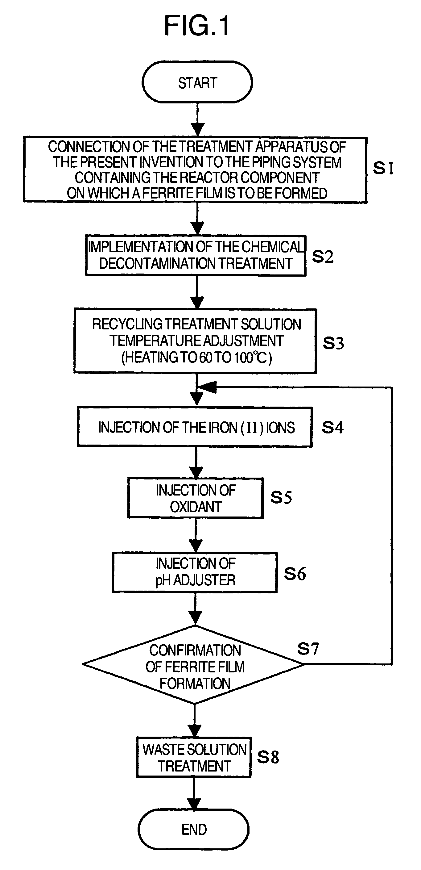
[0127]This system has basically the same work flow with respect to the chemical decontamination and the formation of the ferrite film as that shown in FIG. 1, except that the treatment solution is alternately transferred to the 2 recycling lines 22 (hereinafter “Line A” and “Line B”, respectively) in the following manner so that these lines can be simultaneously treated for the formation of the ferrite film.
[0128]In the apparatus of Example 1 (see FIG. 8), the ferrite film formation apparatus 30 and recycling line 22 are connected to each other by 2 lines. In the system of Example 2 (see FIG. 10), on the other hand, the ferrite film formation apparatus 30 is connected, by one line, to each of ...
example 3
[0133]FIG. 11 illustrates a system schematic of Example 3. The system of the embodiment of Example 3 has basically the same devices and their arrangement as that of the embodiment of Example 1 illustrated in FIG. 7, except that it has the bubbling unit 71 for bubbling the treatment solution in the surge tank 31 and the first agent in the agent tank 45 with an inert gas (e.g. nitrogen).
[0134]Bubbling the first agent and the treatment solution in the surge tank with an inert gas removes the dissolved oxygen from each solution, thereby making them essentially oxygen-free. This accelerates the ferrite film forming reactions by suppressing formation of the iron (III) ions in each solution which has no contribution to ferrite film formation.
PUM
| Property | Measurement | Unit |
|---|---|---|
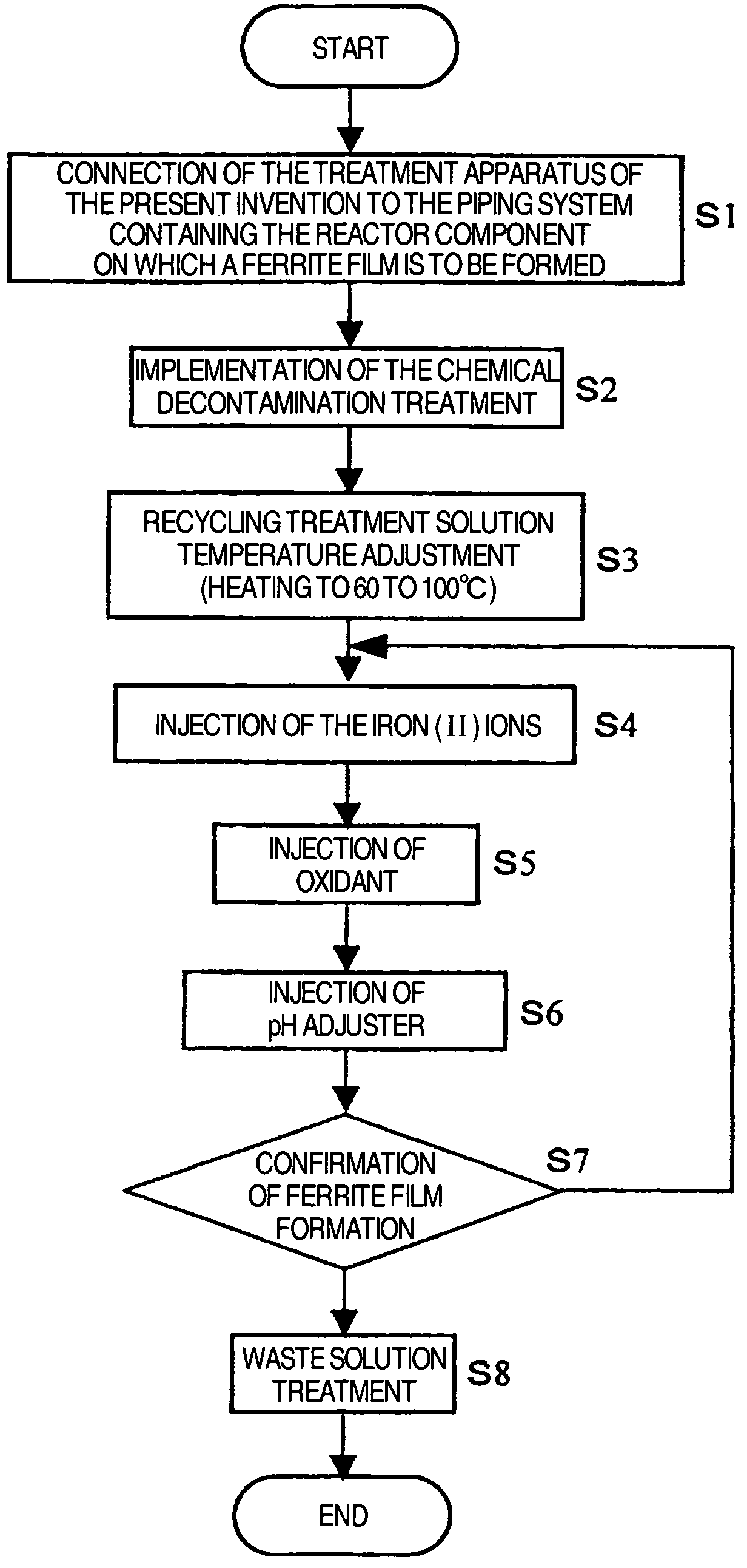
| operating temperature | aaaaa | aaaaa |
| temperature | aaaaa | aaaaa |
| temperature | aaaaa | aaaaa |
Abstract
Description
Claims
Application Information
 - R&D
- Intellectual Property
- Life Sciences
- Materials
- Tech Scout
- Unparalleled Data Quality
- Higher Quality Content
- 60% Fewer Hallucinations
Browse by: Latest US Patents, China's latest patents, Technical Efficacy Thesaurus, Application Domain, Technology Topic, Popular Technical Reports.
© 2025 PatSnap. All rights reserved.Legal|Privacy policy|Modern Slavery Act Transparency Statement|Sitemap|About US| Contact US: help@patsnap.com


