Eureka AIR delivers breakthrough ideas for toughest innovation challenges, trusted by R&D personnel around the world.

Vehicle seat with slide valve

a technology of seat frame and valve, which is applied in the direction of vehicle seats, seating furniture, vehicle arrangements, etc., can solve the problems of low manufacturing cost, and achieve the effects of improving damping properties, low air throughput, and good oscillatory properties

Active Publication Date: 2010-10-12
GRAMMER AG
View PDF5 Cites 21 Cited by
  • Summary
  • Abstract
  • Description
  • Claims
  • Application Information

AI Technical Summary

Benefits of technology

[0006]The core concept of the invention is, in a vehicle seat with a height-adjustable seat frame which comprises at least two seat frame parts which can move relative to one another and at least one fluid spring arranged between the seat frame parts and a base for height adjustment purposes, with at least one control device which is provided for influencing the fluid spring and which comprises at least one valve device with control valves which is attached to the first seat frame part and is designed to control fluid flows for the fluid spring, and also a control element which is provided on a second seat frame part and is designed to actuate the control valves, so that a height adjustment and / or damping oscillatory movement of the vehicle seat is ensured, the valve device comprises an internally cylindrical component with at least one rod element arranged displaceably therein as a control element. The rod element is provided with at least one fluid intake and discharge opening which can selectively be assigned to one of the control valves by a relative displacement of the cylindrical component and the rod element with respect to one another. Such a slide valve, which is preferably arranged next to a damping element, not only advantageously allows a precise adaptation of the quantity of air supplied to and discharged from the air spring for the current spring travel of the air spring, but also allows a simplified design of such a height adjustment device since there is no longer any need to use control links of complicated construction with latching devices and the like. This also results in low manufacturing costs.
[0009]During a normal oscillatory movement of the vehicle seat, as a result of the proportional excursion of the gas spring relative to the internally cylindrical component, a respectively adapted quantity of air is supplied to or discharged from the gas spring in a targeted manner in order to improve the damping properties thereof. This results in a very good oscillatory property of the vehicle seat in the height direction.
[0010]Preferably, the gas intake and discharge opening on the surface of the rod element is provided with at least one notch extending in the longitudinal direction of the rod element with a deepest point in the centre with reference to the longitudinal direction, wherein according to one preferred embodiment the notch may extend at an angle with respect to the longitudinal direction of the rod element or is formed in the longitudinal direction of the rod element. Due to the different depths, such a notch allows a targeted supply and discharge of air in a desired quantity so that, during a desired, e.g. manual, height adjustment of the vehicle seat, a low air throughput is obtained for a small movement of the actuation element or a single actuation of the height adjustment actuation element. This results in a gentle, precise movement of the vehicle seat undergoing height adjustment towards the desired point.
[0011]Likewise, a medium air throughput is obtained when the height adjustment actuation element is actuated twice, or a high air throughput is obtained when it is actuated three times or in the case of rapid lowering actuation, resulting in a faster movement of the height-adjustable vehicle seat which is slowed upon reaching the desired target position.

Problems solved by technology

This also results in low manufacturing costs.

Method used


Image

  • Vehicle seat with slide valve
  • Vehicle seat with slide valve
  • Vehicle seat with slide valve

Examples


Embodiment Construction

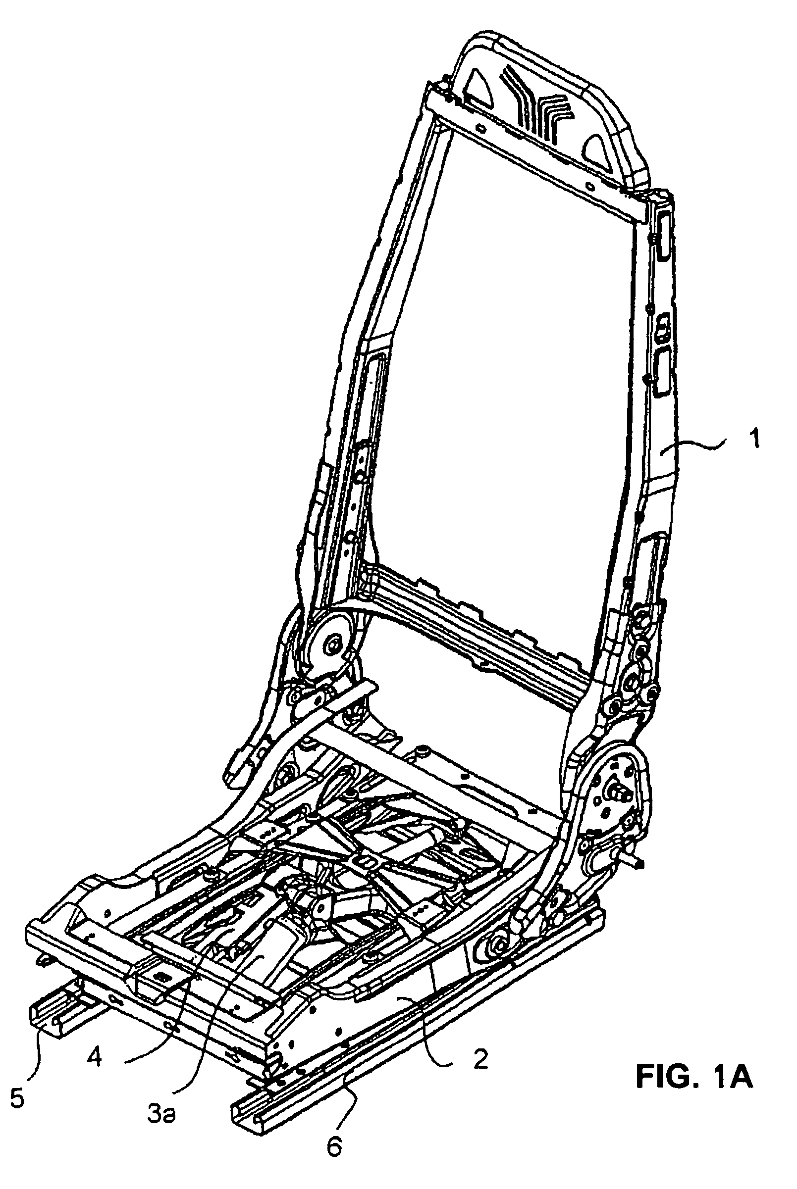
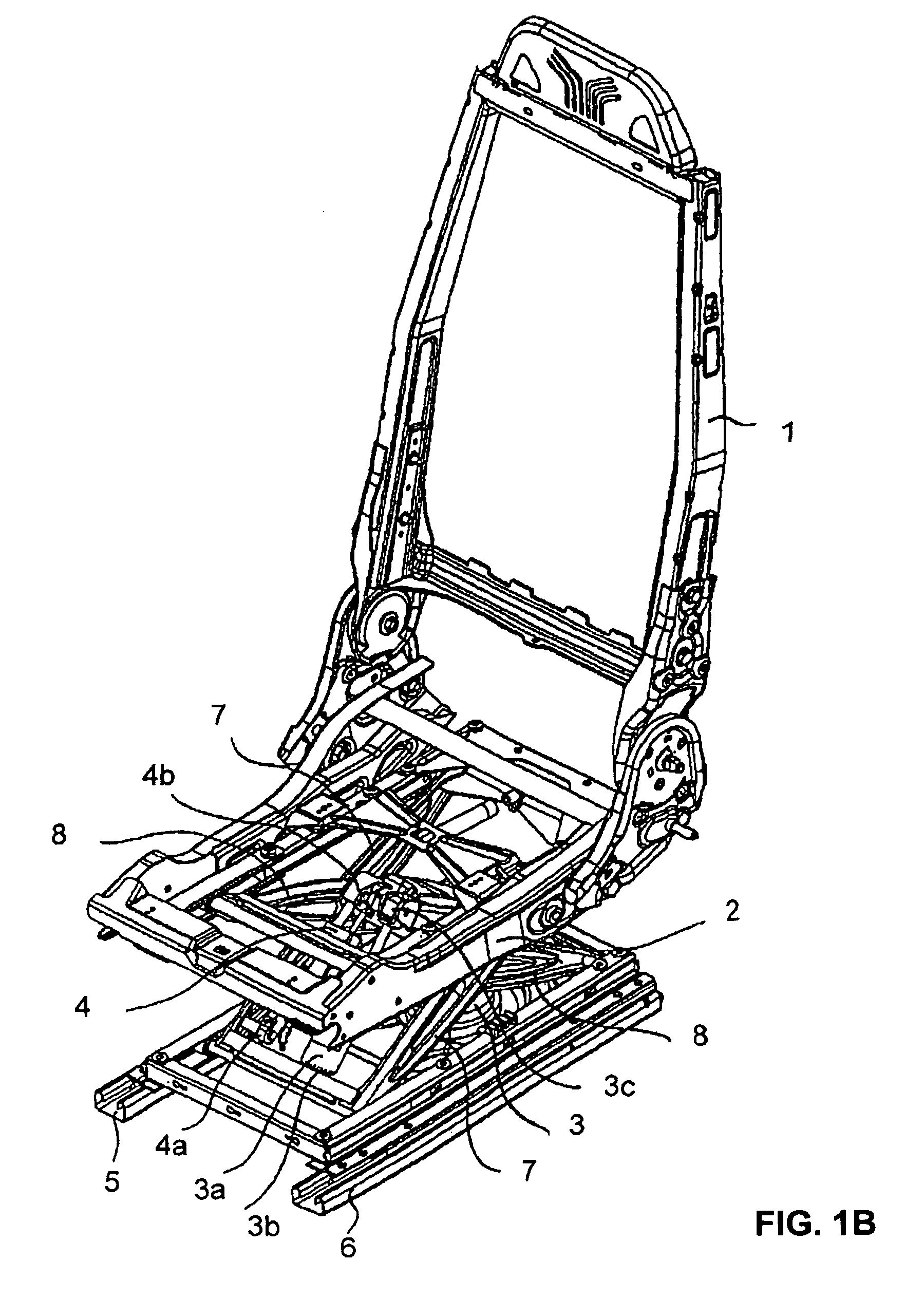
[0039]FIGS. 1A-C show a vehicle seat with a backrest 1 and a seat part 2, which is shown in various height positions. The lowest seat position of the vehicle seat in FIG. 1A shows a folded-together scissors-type seat frame with an air spring designed as a gas spring and with a control device 4 or height adjustment device.

[0040]The air spring 3 (not seen on FIG. 1A; See FIGS. 1B and 1C) is connected by a lower end to a base of the vehicle seat or a body part or another element (not shown) that is fixedly connected to the body, and is connected by an upper end to at least one part of the scissors-type seat frame.

[0041]The seat is arranged on rails 5, 6 such that it can be displaced in the forward and backward direction.

[0042]FIGS. 1B and 1C show the first seat frame part 7 and the second seat frame part 8, wherein both the control device 4 and a spring-type damping element 3a are attached by first ends3b and 4a to the bottom of the first seat frame part 7 and by second, upper ends 3c ...


PUM


Abstract

The invention relates to a vehicle seat with a height-adjustable seat frame which comprises at least two seat frame parts which can move relative to one another and at least one fluid spring, in particular an air spring, arranged on the seat frame parts for height adjustment purposes, with at least one control device which is provided for influencing the fluid spring and which comprises at least one valve device with control valves which is attached to the first seat frame part and is designed to control fluid flows for the fluid spring, and also a control element which is provided on a second seat frame part and is designed to actuate the control valves, so that a height adjustment and / or damping oscillatory movement of the vehicle seat is ensured, wherein the valve device comprises an internally cylindrical component with at least one rod element arranged displaceably therein as a control element, wherein at least one fluid intake and discharge opening of the rod element can selectively be assigned to one of the control elements by a relative displacement of the cylindrical component and the rod element with respect to one another.

Description

CROSS REFERENCE TO RELATED APPLICATIONS[0001]This application is a convention application of German Application Serial Number 10 2007 030 467.8, filed Jun. 29, 2007, which application is hereby incorporated by this reference in its entirety.BACKGROUND OF THE INVENTION[0002]The invention relates to a vehicle seat with a height-adjustable seat frame which comprises at least two seat frame parts which can move relative to one another and at least one fluid spring, in particular an air spring, arranged between the seat frame parts for height adjustment purposes, with at least one control device which is provided for influencing the fluid spring and which comprises at least one valve device with control valves which is attached to the first seat frame part and is designed to control fluid flows for the fluid spring, and also a control element which is provided on a second seat frame part and is designed to actuate the control valves, according to the preamble of claim 1.[0003]EP 0 710 60...

Claims


Application Information

Patent Timeline
Patent Type & Authority Patents(United States)
IPC IPC(8): A47C1/00
CPCB60N2/501B60N2/502B60N2/505B60N2/508B60N2/525
Inventor LOREY, KONSTANTINHALLER, ERWINBURGER, THOMAS
Owner GRAMMER AG
Why Eureka
Eureka Blog
Learn More