
Radar system having dual band polarization versatile active electronically scanned lens array

a technology of electronic scanning and radar systems, applied in the direction of polarised antenna unit combinations, instruments, reradiation, etc., can solve the problems of impracticality of conventional architecture, concomitant module count, array cost, etc., to reduce the number of active elements, reduce the cost of the array, and low noise

Active Publication Date: 2010-10-05
RAYTHEON CO
View PDF29 Cites 14 Cited by
  • Summary
  • Abstract
  • Description
  • Claims
  • Application Information

AI Technical Summary

Benefits of technology

[0002]The present invention provides methods and apparatus for radar systems having polarization versatile Active Electronically Scanned Lens Array (AESLA) that reduce the number of active elements requiring RF power and low noise amplification as compared with conventional configurations. Since fewer active elements are required, the cost of the array is substantially decreased. In addition, dual band operation, combined with the ability to synthesize arbitrary polarizations for one or both bands, provides great flexibility for multi-function radar missions. A shared antenna aperture reduces space required for the radar system and allows reuse of the back-end electronics which saves on overall system development cost.

Problems solved by technology

The cost of a phased array system is proportional to the number of active elements making up the AESA and the T / R modules typically represent a significant portion of the system cost.
While dual band operation in a shared aperture would be highly desirable in many applications, the concomitant module count and array cost is impractical using conventional architectures.

Method used


Image

  • Radar system having dual band polarization versatile active electronically scanned lens array
  • Radar system having dual band polarization versatile active electronically scanned lens array
  • Radar system having dual band polarization versatile active electronically scanned lens array

Examples


Embodiment Construction

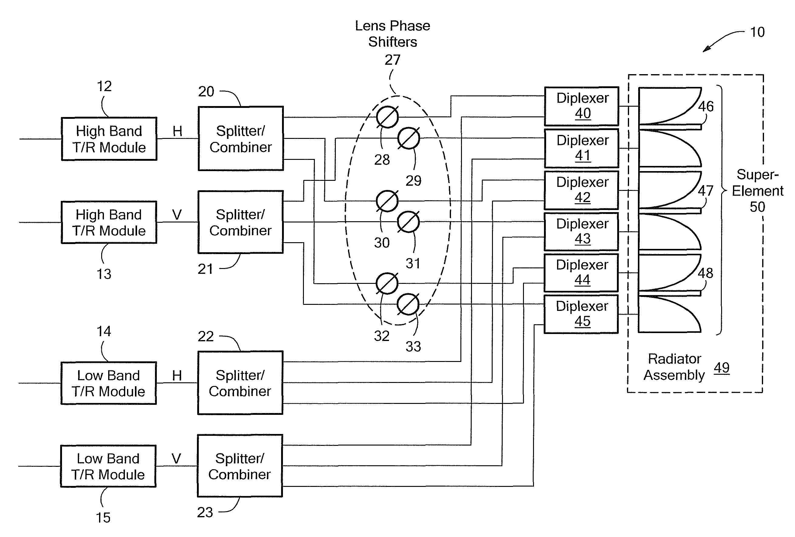
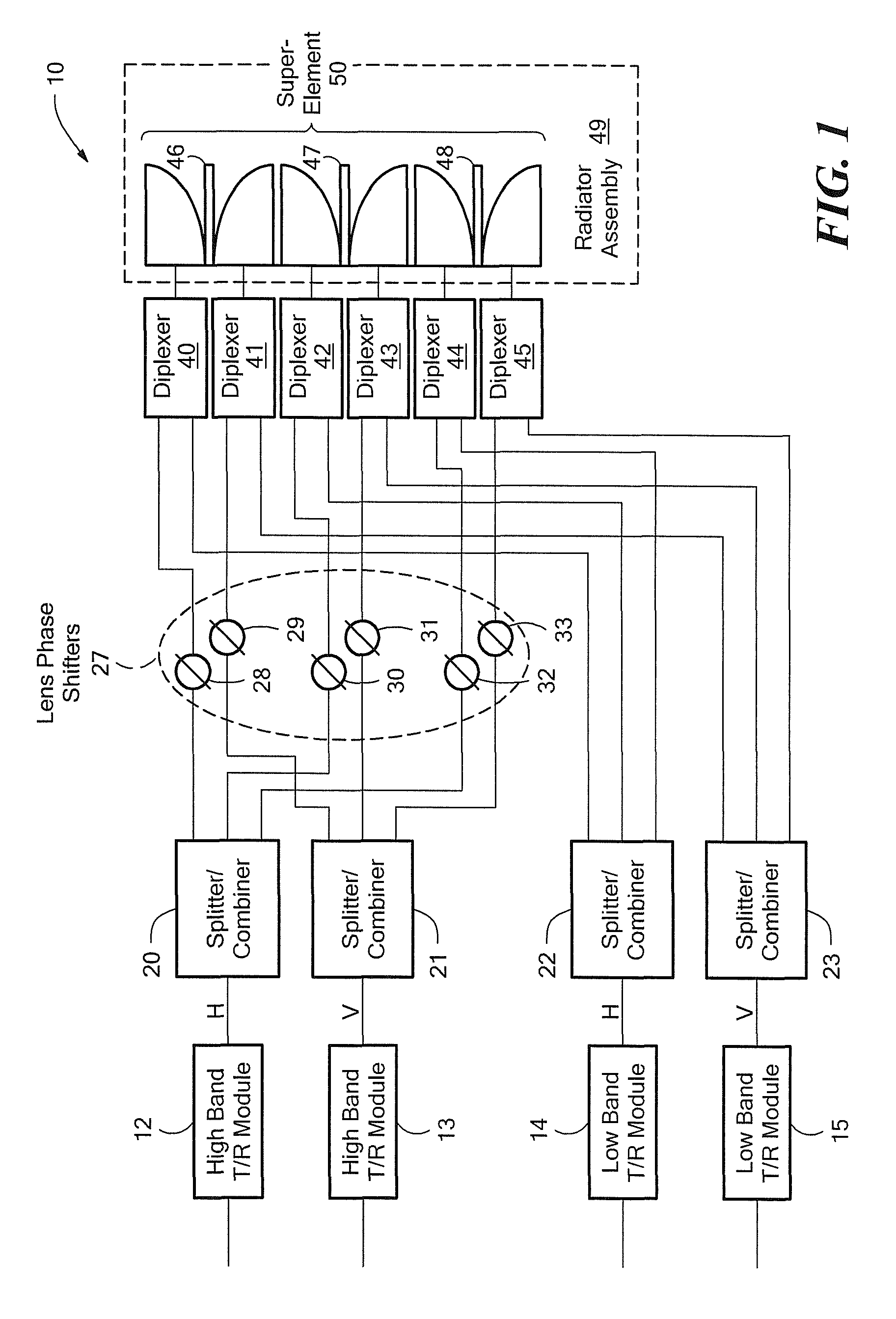
[0014]FIG. 1 shows a block diagram of a radar system having a dual band polarization versatile active electronically scanned lens array (AESLA) 10 in accordance with an exemplary embodiment of the present invention, which is designed to provide full field of view (FFOV) electronic scanning for first and second frequency bands in a shared aperture. In the illustrated embodiment, four transmit / receive (T / R) modules 12-15 are provided, one for each of the two orthogonal polarizations (Horizontal (H) and Vertical (V)), and one for each of the two bands, e.g., high frequency X band and lower frequency S band. The signal output from each of the T / R modules 12, 13, 14 and 15 is fed to splitter / combiners 20, 21, 22, 23, respectively, for splitting 3 ways. Splitter / combiners 20, 21 feed the high X band signals to phase shifters 28, 29, 30, 31, 32, 33 which provide the FFOV lens array scanning for the high frequency X band.

[0015]The outputs from the phase shifters 28-33 are fed to one of dipl...


PUM


Abstract

A radar system comprises a first transmit / receive module for a first frequency band and a first polarization, a second transmit / receive module for the first frequency band and a second polarization orthogonal to the first polarization, a third transmit / receive module for a second frequency band and the first polarization, a fourth transmit / receive module for the second frequency band and the second polarization orthogonal to the first polarization, a first plurality of splitter / combiners to receive outputs from the first and second transmit / receive modules, a second plurality of splitter / combiners to receive outputs from the third and fourth transmit / receive modules, a plurality of lens phase shifter pairs to receive outputs from the first plurality of splitter / combiners, a plurality of diplexers to receive signals from the plurality of lens phase shifter pairs and from the second plurality of splitter / combiners, and, a radiator assembly including a series of radiator elements coupled to the plurality of diplexers.

Description

BACKGROUND OF THE INVENTION[0001]Full field of view (FFOV) active electronically scanned arrays (AESA) are typically architected with transmit and receive amplifiers and corresponding phase and amplitude control for every element of the phased array system. This functionality can be provided by a transmit / receive (T / R) module. The element spacing is on the order of one-half the wavelength of the highest operating frequency. This leads to many thousands of elements for applications requiring large apertures. The cost of a phased array system is proportional to the number of active elements making up the AESA and the T / R modules typically represent a significant portion of the system cost. While dual band operation in a shared aperture would be highly desirable in many applications, the concomitant module count and array cost is impractical using conventional architectures.SUMMARY OF THE INVENTION[0002]The present invention provides methods and apparatus for radar systems having polar...

Claims


Application Information

Patent Timeline
Patent Type & Authority Patents(United States)
IPC IPC(8): G01S7/02G01S13/00
CPCG01S7/025G01S7/034H01Q3/26
Inventor SARCIONE, MICHAEL G.RYPYSC, DANIEL F.CHANG, KAICHIANGHOLLEY, JEFFREY R.ROWLAND, LANDON L.
Owner RAYTHEON CO
Learn More