
Computer interaction based upon a currently active input device

a computer and input device technology, applied in computing, instruments, electric digital data processing, etc., can solve the problems of difficult to interact with the computer, many dropdown menus are very difficult for right-handed users to use, and scroll bars are difficult to manipulate for left-handed users, so as to facilitate an improved user interaction experience

Inactive Publication Date: 2010-09-21
MICROSOFT TECH LICENSING LLC
View PDF14 Cites 17 Cited by
  • Summary
  • Abstract
  • Description
  • Claims
  • Application Information

AI Technical Summary

Benefits of technology

The present invention provides a system and method that detects the type of input device used by a user and modifies the data interaction model accordingly to improve the user's experience. This allows for better interaction with the program, making it easier for the user to interact with it. The system analyzes data from multiple input devices, such as pen, touch, keyboard, and mouse, and selects the most recently active input device as the currently active input device. The program then changes its user interface behavior and appearance based on the selected input device. This results in a more efficient and effective user interaction.

Problems solved by technology

However, each input device has unique physical and ergonomic characteristics that result in various challenges.
One important set of challenges arises because of the way various input devices interact with the content displayed on the screen.
Thus, when using the pen, a user's hand often blocks a portion of the screen, making it difficult to interact with the computer.
As one example, many dropdown menus are very difficult for right-handed users to use with a pen because they drop down so as to be obscured by the user's right hand.
Scroll bars can be difficult to manipulate for left-handed users.
In sum, these problems, as well as many other similar and related problems, are experienced by computer users as a result of the variety of alternative input devices.

Method used


Image

  • Computer interaction based upon a currently active input device
  • Computer interaction based upon a currently active input device
  • Computer interaction based upon a currently active input device

Examples


Embodiment Construction

Exemplary Operating Environment

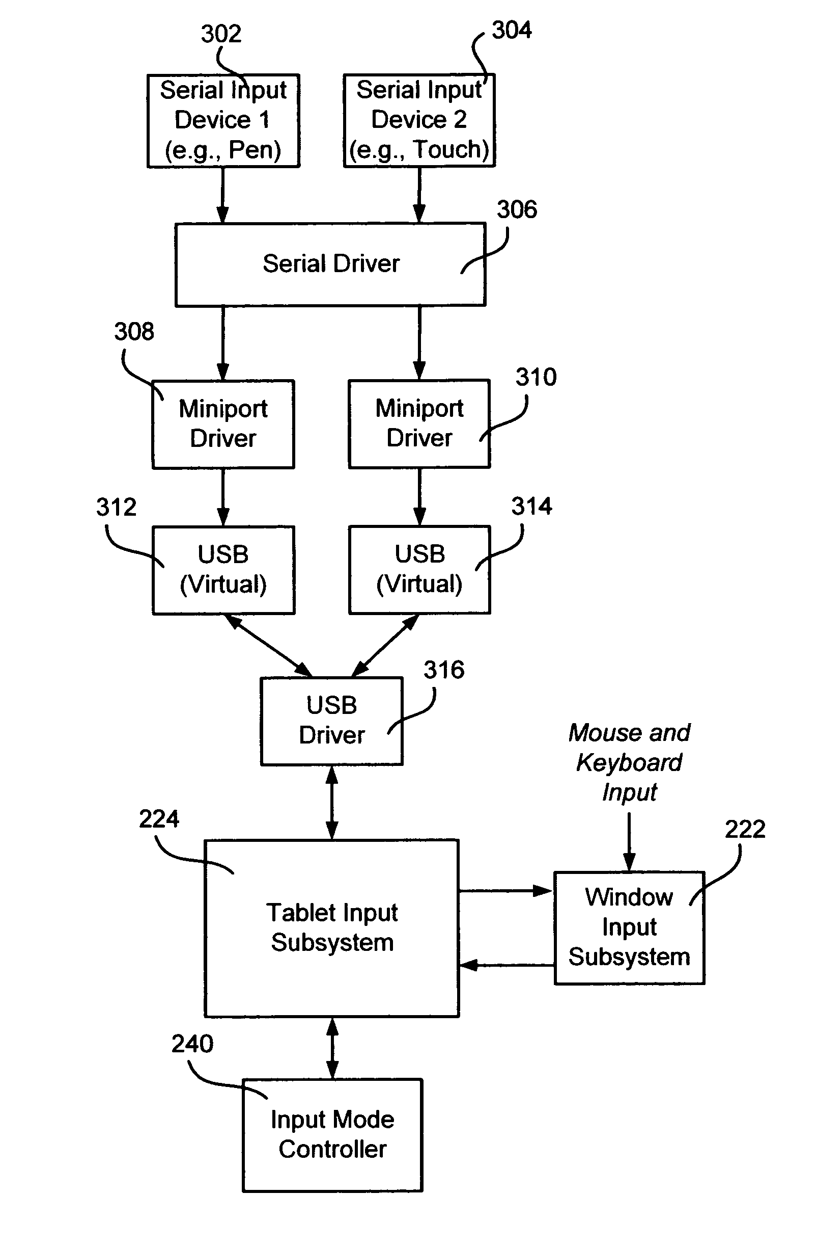
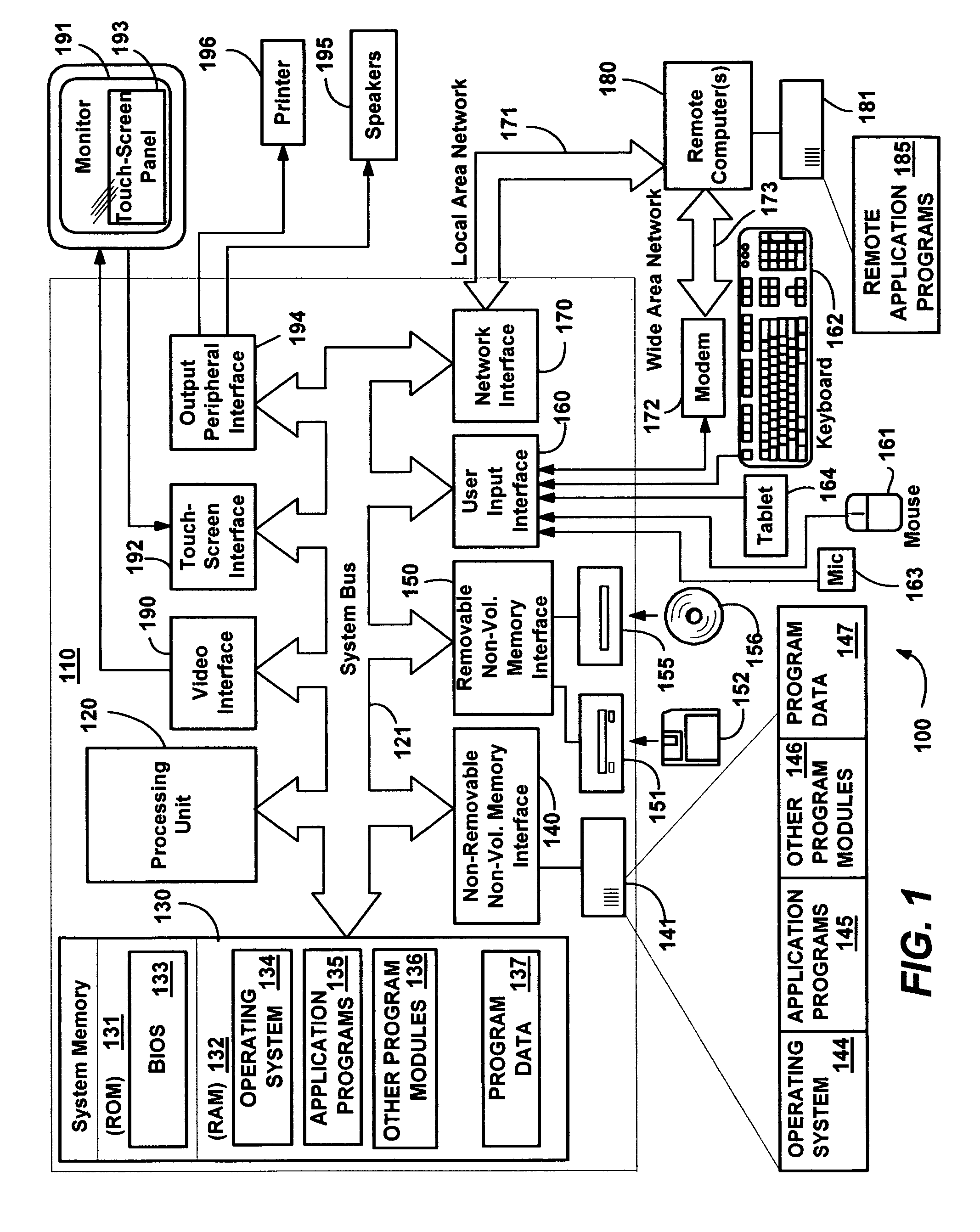
[0019]FIG. 1 illustrates an example of a suitable computing system environment 100 on which the invention may be implemented. The computing system environment 100 is only one example of a suitable computing environment and is not intended to suggest any limitation as to the scope of use or functionality of the invention. Neither should the computing environment 100 be interpreted as having any dependency or requirement relating to any one or combination of components illustrated in the exemplary operating environment 100.

[0020]The invention is operational with numerous other general purpose or special purpose computing system environments or configurations. Examples of well known computing systems, environments, and / or configurations that may be suitable for use with the invention include, but are not limited to, personal computers, server computers, hand-held or laptop devices, tablet devices, multiprocessor systems, microprocessor-based systems, set ...


PUM


Abstract

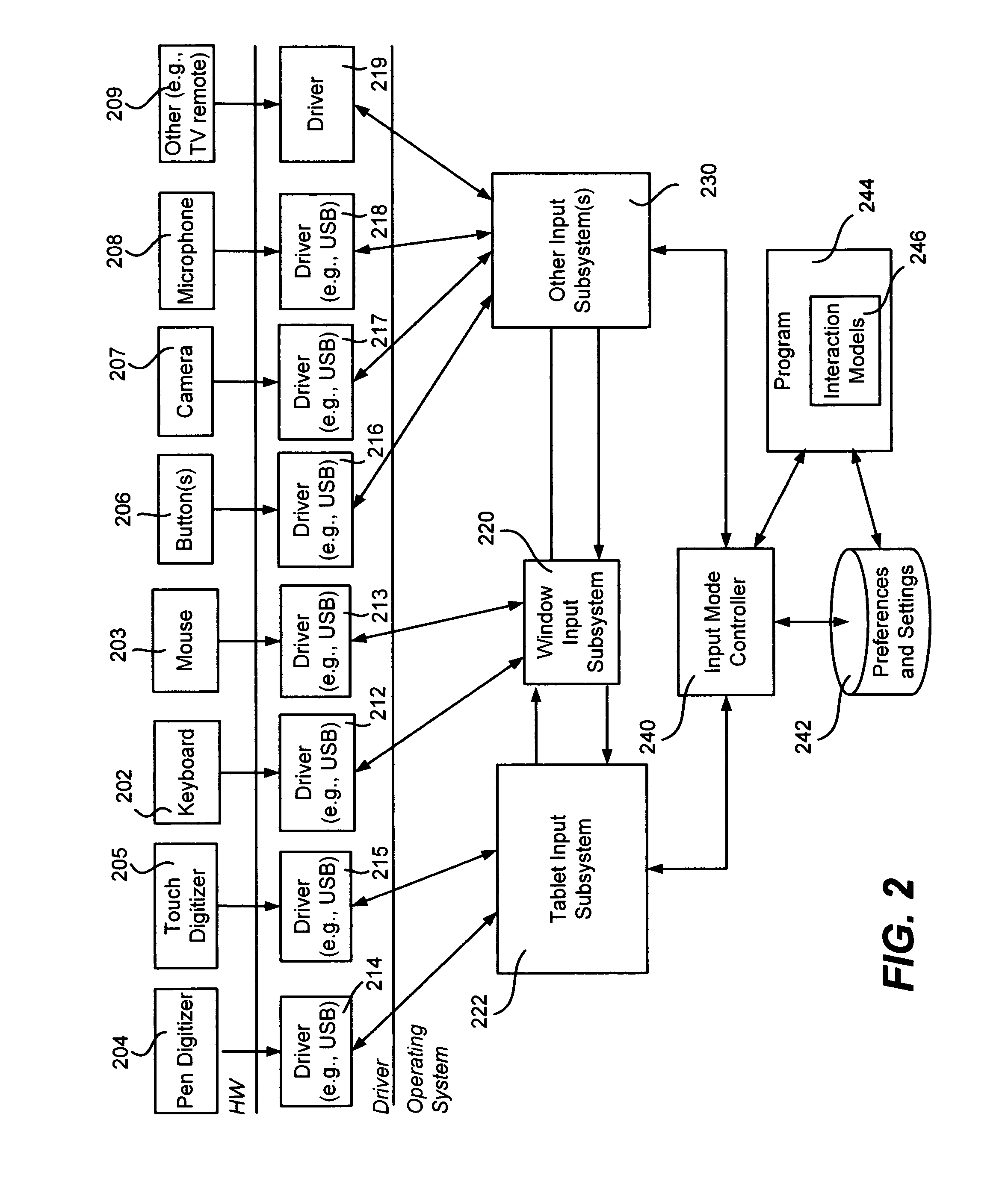
Described is a computer-implemented system and method that dynamically detects which input device (e.g., pen or mouse) is currently in use, and based on the device, varies a program's user interaction model to better optimize the user's ability to interact with the program via that input device. A tablet input subsystem receives pen and touch data, and also obtains keyboard and mouse data. The subsystem analyzes the data and determines which input device is currently active. The active device is mapped to an interaction model, whereby different user interface appearances, behaviors and the like may be presented to the user to facilitate improved interaction. For example, a program may change the size of user interface elements to enable the user to more accurately scroll and make selections. Timing, tolerances and thresholds may change. Pen hovering can become active, and interaction events received at the same location can be handled differently.

Description

FIELD OF THE INVENTION[0001]The present invention relates generally to computing devices, and more particularly to user interaction with computing devices.BACKGROUND OF THE INVENTION[0002]Contemporary computing devices allow users to input information in a number of ways, including by keyboard, by one or more types of pointing devices, and by dedicated hardware buttons (typically on portable devices). Voice data and eye movement data (e.g., gaze detection) are other types of data users can input into computer systems via microphones and cameras, respectively.[0003]With respect to pointing devices, a computer system may receive user input from a mouse and / or a touchpad, and if configured with a digitizer, by sensing stylus (pen) proximity and touch, e.g., entered via a pen or a finger. Some personal computers, such as tablet-based personal computers, have the digitizer built into the display screen. This is highly beneficial for many users, as such a computing device can be operated ...

Claims


Application Information

Patent Timeline
Patent Type & Authority Patents(United States)
IPC IPC(8): G06F3/00G06F3/048G06F3/038
CPCG06F3/038G06F3/0481G06F3/0488
Inventor FOX, ERIC B.RIMAS-RIBIKAUSKAS, EMILY K.JARRETT, ROBERT J.KEELY, LEROY B.
Owner MICROSOFT TECH LICENSING LLC
Learn More