
Tandem filters using frequency selective surfaces for enhanced conversion efficiency in a thermophotovoltaic energy conversion system

a technology of thermophotovoltaic energy conversion and frequency selective surfaces, applied in the field of filters, can solve the problems of reducing the power density of the electrical output surface, parasitically absorbing heat, and reducing the above bandgap energy incident on the tpv device, and achieves high reflection, and high transmission of above bandgap energy

Inactive Publication Date: 2010-09-07
THE UNITED STATES AS REPRESENTED BY THE DEPARTMENT OF ENERGY
View PDF10 Cites 9 Cited by
  • Summary
  • Abstract
  • Description
  • Claims
  • Application Information

AI Technical Summary

Benefits of technology

"The present invention is a new combination of a frequency selective surface and an interference filter that solves the limitations of each individual component. The frequency selective surface allows for high transmission of energy above the bandgap and high reflection of energy below the bandgap, while the interference filter maintains high transmission of energy above the bandgap and provides high reflection of energy below the bandgap with a sharp transition. This combination of filters provides a more cost-effective and potentially higher performance alternative to the interference filter / plasma filter tandem concept."

Problems solved by technology

Photons with energy less than the semiconductor bandgap cannot be converted to electrical energy and, therefore, are parasitically absorbed as heat.
The significant issue with this type of selective radiator for some applications is the reduction of above bandgap energy incident on the TPV device compared with TPV systems that employ high emissivity blackbody radiators.
This reduction in available above bandgap energy causes a reduced electrical output surface power density.
A critical issue associated with this approach is the amount of below bandgap energy parasitically absorbed during transit through the TPV device.
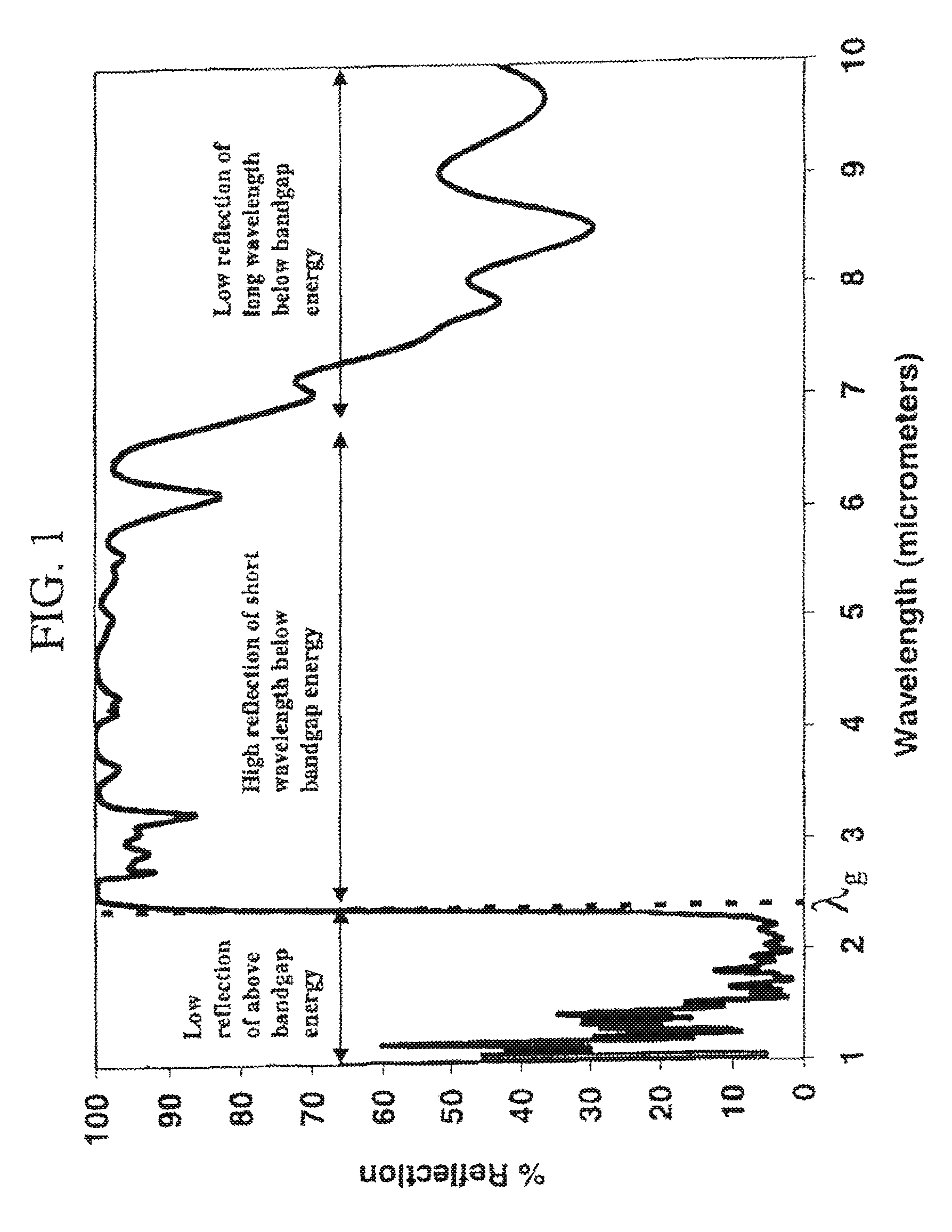
In most TPV systems, 25% of the blackbody radiation is emitted with wavelengths greater than the reflective range of a practical interference filter, therefore, an interference filter alone does not meet all of the desired filter characteristics described above.
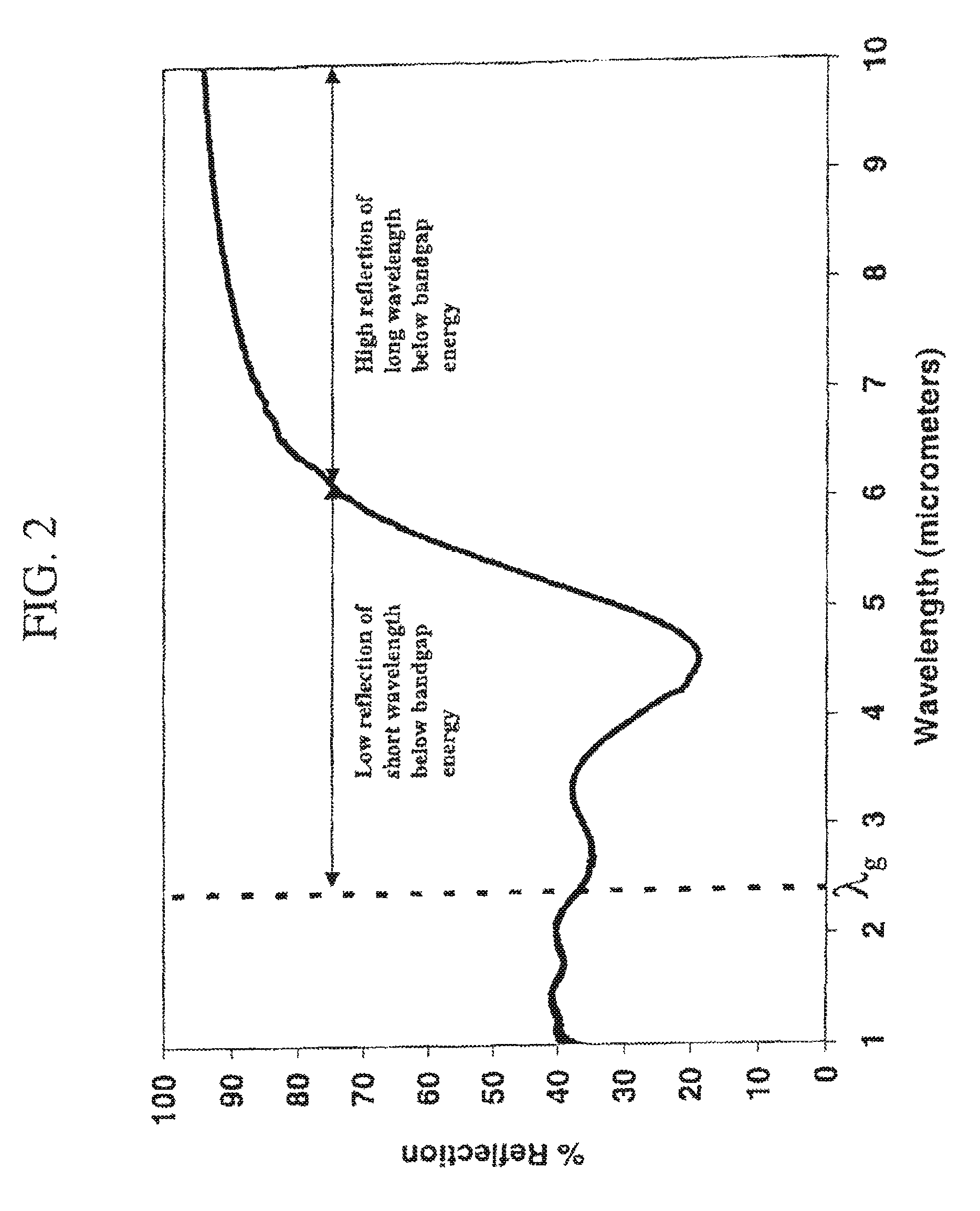
Therefore, a plasma filter with plasma wavelength approximately equal to the semiconductor device bandgap would provide high reflection for below bandgap energy, but would also exhibit a large amount of parasitic absorption of above bandgap energy.
Shilling the plasma wavelength of the plasma filter to longer wavelengths reduces the parasitic absorption of above bandgap energy, but also reduces the reflectivity of shorter wavelength below bandgap energy.
As shown in FIG. 2, the typical plasma filter alone does not meet all of the desired filter characteristics described above.
However, a performance tradeoff exists between the transmission of above bandgap energy and the reflection of short wavelength below bandgap energy.
FSS filters that have high transmission of above bandgap energy typically do not provide the desired sharp transition to high reflection and, therefore, do not have high reflection of short wavelength below bandgap energy.
Although this filter provides high reflection of all below bandgap energy, it suffers from very low integrated transmission of above bandgap energy caused by high above bandgap reflection.
Therefore, frequency selective surfaces designed to maximize reflection of below bandgap energy do not meet all of the desired filter characteristics described above.
Although this filter provides high transmission of above bandgap energy, it does not exhibit an abrupt transition from low reflection (high transmission) to high reflection and, therefore, does not provide high reflection for short wavelength below bandgap energy.
Therefore, frequency selective surfaces designed to maximize transmission of above bandgap energy do not meet all of the desired filter characteristics described above.

Method used


Image

  • Tandem filters using frequency selective surfaces for enhanced conversion efficiency in a thermophotovoltaic energy conversion system
  • Tandem filters using frequency selective surfaces for enhanced conversion efficiency in a thermophotovoltaic energy conversion system
  • Tandem filters using frequency selective surfaces for enhanced conversion efficiency in a thermophotovoltaic energy conversion system

Examples


Embodiment Construction

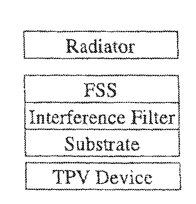
[0031]The present invention constitutes a novel combination of a frequency selective surface and an interference filter in a tandem configuration to overcome the limitations of each of the individual components. In the preferred embodiment of the present invention, the typical interference filter is disposed on top of the typical FSS such that photons from the radiator are first incident on the interference filter. In the preferred embodiment of the present invention, the FSS tandem filter may be fabricated in four configurations. In the first configuration, illustrated in FIG. 7A, the typical FSS is fabricated on a substrate and the typical interference filter is deposited directly on top of the typical FSS filter. The resulting FSS tandem filter is then mounted to a TPV device. In a second configuration, illustrated in FIG. 7B, the typical interference filter is deposited on the opposite side of the substrate that the typical FSS filter is fabricated upon and then the resulting FS...


PUM


Abstract

This invention relates to the field of thermophotovoltaic (TPV) direct energy conversion. In particular, TPV systems use filters to minimize parasitic absorption of below bandgap energy. This invention constitutes a novel combination of front surface filters to increase TPV conversion efficiency by reflecting useless below bandgap energy while transmitting a very high percentage of the useful above bandgap energy. In particular, a frequency selective surface is used in combination with an interference filter. The frequency selective surface provides high transmission of above bandgap energy and high reflection of long wavelength below bandgap energy. The interference filter maintains high transmission of above bandgap energy and provides high reflection of short wavelength below bandgap energy and a sharp transition from high transmission to high reflection.

Description

CROSS REFERENCE TO RELATED APPLICATION[0001]This application is a Division of U.S. application Ser. No. 10 / 217,441 filed Aug. 14, 2002 now U.S. Pat. No. 7,166,797 which claims priority from U.S. Provisional Application Ser. No. 60 / 314,174 filed Aug. 23, 2001.FIELD OF INVENTION[0002]This invention was made under a contract with the U.S. Department of Energy. The present invention relates to the field of thermophotovoltaic direct energy conversion. In particular, the present invention relates to filters used to reduce parasitic absorption of below bandgap energy in thermophotovoltaic systems.BACKGROUND[0003]Thermophotovoltaic (TPV) energy systems convert thermal energy to electric power using the same principle of operation as solar cells. In particular, a heat source radiatively emits photons that are incident on a semiconductor TPV device with an energy (E) spectrum that can be characterized by Planck's blackbody distribution modified to account for the radiator surface spectral emi...

Claims


Application Information

Patent Timeline
Patent Type & Authority Patents(United States)
IPC IPC(8): H01L31/052
CPCG02B5/204G02B5/208H02S10/30H01L31/0232G02B5/285Y02E10/52H01L31/02165Y02E10/50
Inventor DZIENDZIEL, RANDOLPH J.BALDASARO, PAUL F.DEPOY, DAVID M.
Owner THE UNITED STATES AS REPRESENTED BY THE DEPARTMENT OF ENERGY
Learn More