Magnet protection mechanism for magnet body in rotor and magnet protection method

a magnet protection mechanism and magnet protection technology, applied in the direction of magnetic bodies, magnetic circuit rotating parts, magnetic circuit shapes/forms/construction, etc., can solve the problems of deteriorating a magnetic characteristic of the magnet component and reducing the durability of the magnet component such as the claw pole and the permanent magnet, and achieve the effect of easy detachment of the magnetic covering member

Inactive Publication Date: 2010-08-31
DENSO CORP
View PDF36 Cites 8 Cited by
  • Summary
  • Abstract
  • Description
  • Claims
  • Application Information

AI Technical Summary

Benefits of technology

[0011]It is an object of the present invention to provide a magnet protection mechanism and a magnet protection method capable of protecting adhesion of magnetic powders onto magnet bodies such as permanent magnets placed in a rotor with a simple manner before incorporating a stator into a rotary electric machine.

Problems solved by technology

Although the vehicle alternator of the Lundell type rotor core having such a configuration increases its output power by increasing the magnitude of magnetic flux generated by additionally incorporating permanent magnets into the rotor core when compared with a vehicle alternator of a same volume without incorporating any additional permanent magnets, such a configuration deteriorates a magnetic characteristic of and decreases the durability of the magnet components such as the claw poles and the permanent magnets because of the adhesion of magnet powders generated during manufacturing processes of the rotor core onto the surface of the magnet component, in particular, of the permanent magnet.

Method used


Image

  • Magnet protection mechanism for magnet body in rotor and magnet protection method
  • Magnet protection mechanism for magnet body in rotor and magnet protection method
  • Magnet protection mechanism for magnet body in rotor and magnet protection method

Examples


first embodiment

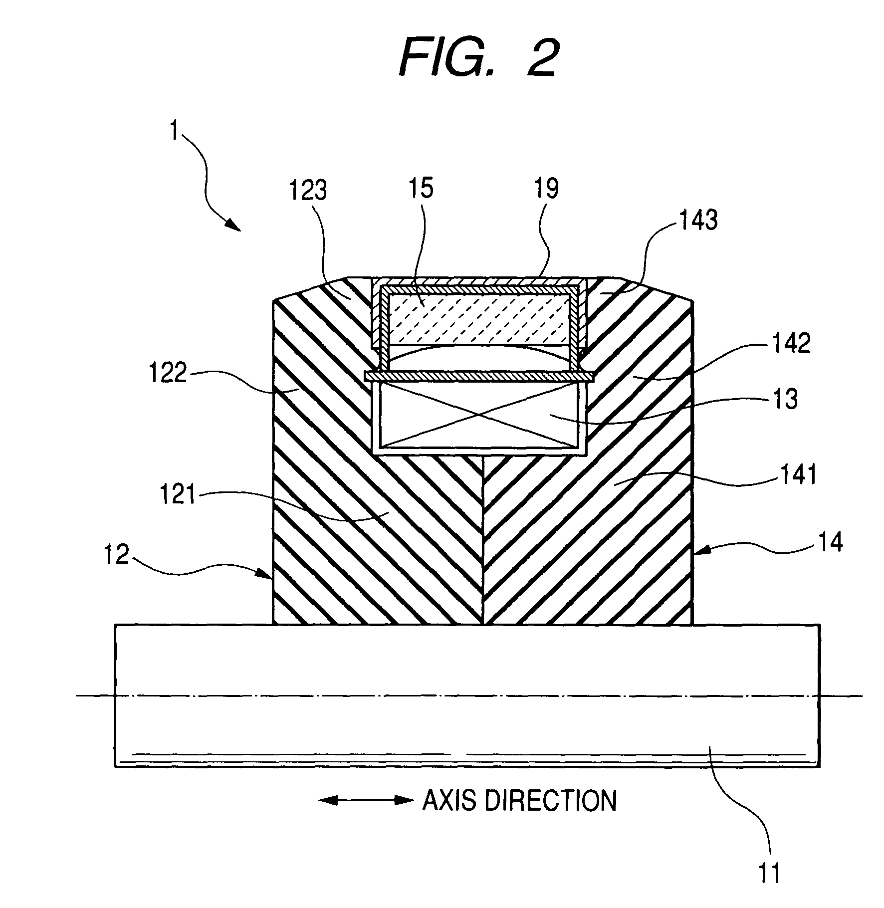
[0050]A description will now be given of the magnet protection mechanism and a magnet protection method before the rotor 1 such as a Lundell type rotor core is incorporated into a vehicle alternator with reference to FIG. 2, FIG. 3, and FIG. 4.

[0051]FIG. 4 is an enlarged partial sectional diagram in the axis direction showing the permanent magnet 15 (as a magnetic body) and the magnet covering member 19 shown in FIG. 3 according to the first embodiment;

[0052]Before incorporating the pole cores 12 and 14 of the rotor 1 into the stator core 21 of a vehicle alternator, the pole cores 12 and 14 shown in FIG. 3 are magnetized by using the permanent magnets 15 of the permanent magnet portion that have been magnetized in advance. Because it is difficult to form a closed magnetic path in the pole cores 12 and 14 and the stator core 21 in the vehicle alternator before such an incorporating process, a magnet field is generated widely in the peripheral space of the pole cores 12 and 14 and the...

second embodiment

[0059]A description will now be given of the magnet protection mechanism according to the second embodiment of the present invention with reference to FIG. 5 to FIG. 8.

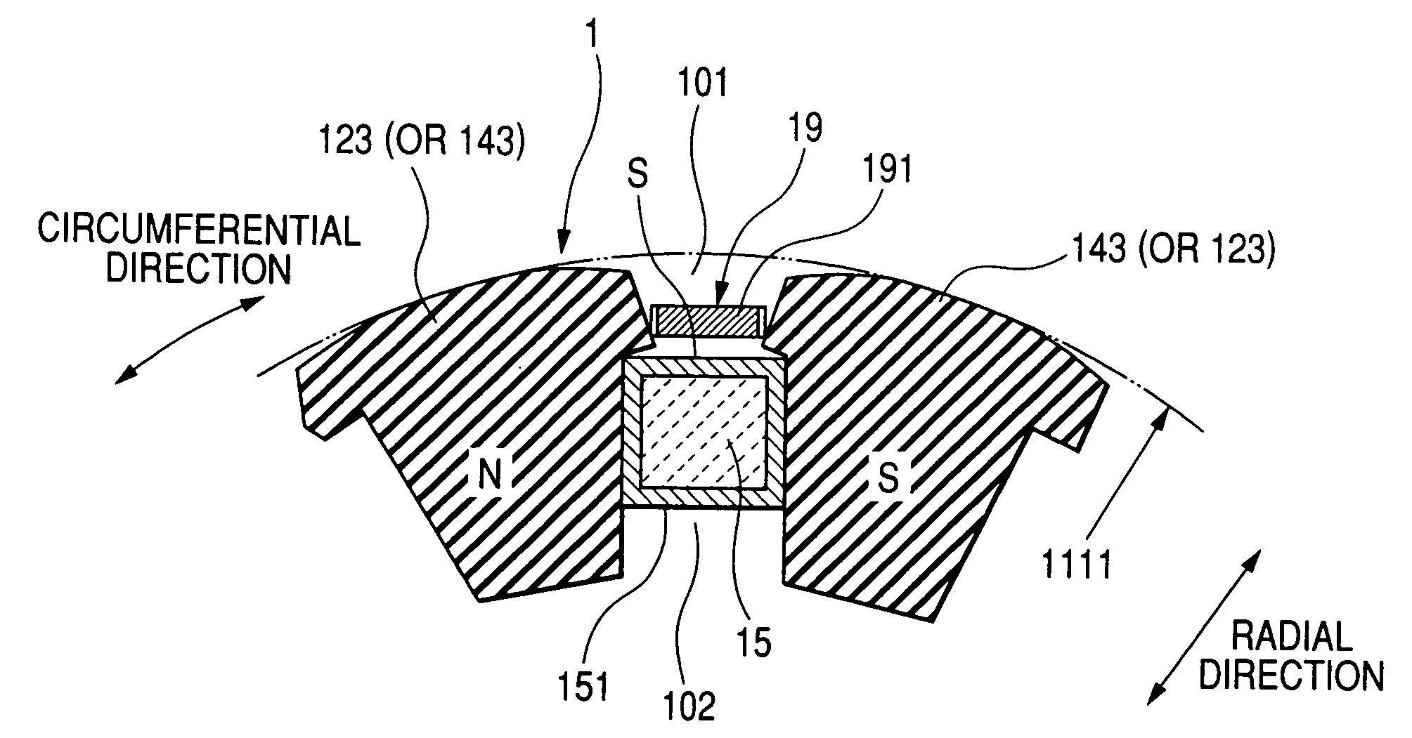
[0060]Similar to the first embodiment, the pole cores 12 and 14 of the rotor 1 shown in FIG. 3 are magnetized by the permanent magnets 15 that have been magnetized in advance before the incorporating process of the pole cores 12 and 14 of the rotor 1 into the stator core 21. At this manufacturing process, like the first embodiment, because it is impossible to form a closed magnet path in the pole cores 12 and 14 and the stator core 21 in the vehicle alternator, a leakage magnet field is generated widely in the peripheral space of the pole cores 12 and 14 and the permanent magnets 15. Such a leakage magnet field is concentrated in both gaps 101 and 102 between the adjacent claw poles 124 (or 143) and 143 (or 123). The distance between the adjacent claw poles 123 and 143 that are magnetized in an opposite direction beco...

first modification

(First Modification)

[0073]The first and second embodiments described above adopt a Lundell type rotor core as the rotor 1. The present invention is not limited by those embodiments. For example, the concept of the present invention regarding the magnet covering members 19 and 190 can be applied to a rotor having a configuration in which an outer peripheral surface of each of permanent magnets that are placed on a rotor core is exposed to the outside of the rotor core, such as a rotor mounted on a surface permanent magnet (SPM) synchronous machine.


PUM


Abstract

A magnet covering member made of a soft steel plate covers an outer surface of a magnetized permanent magnet placed in a rotor core of a rotor. The magnet covering member is detached from the permanent magnet when the rotor is incorporated into a stator of an alternator during an alternator assembling process. Because of a soft magnetic characteristic of the magnet covering member, an outer magnetic field generated by the permanent magnet placed between adjacent claw poles of the rotor core makes a magnetic short-circuit, and a magnetic attracting phenomenon caused by such a magnetic field is thereby reduced. The soft magnetic characteristic of the magnet covering member also serves to support the rotor.

Description

[0001]This is a Divisional of U.S. patent application Ser. No. 11 / 503,967 filed on Aug. 15, 2006, which is hereby incorporated herein by reference in its entirety. This application claims priority to Japanese Patent Application No. 2005-253737 filed on Sep. 1, 2005, which is hereby incorporated herein by reference in its entirety.BACKGROUND OF THE INVENTION[0002]1. Field of the Invention[0003]The present invention generally relates to a magnet protection mechanism and a magnet protection method capable of protecting magnet bodies such as permanent magnets, from magnetic powders and dust, placed in a rotor of an inner-rotor type vehicle alternator.[0004]2. Description of the Related Art[0005]There is a conventional technique to increase the magnitude of or to support a magnetic flux of a field current at each claw pole by a magnetic flux of a permanent magnet additionally placed between adjacent claw poles in a Lundell type rotor core of a rotary electric machine such as a vehicle al...

Claims


Application Information

Patent Timeline
Patent Type & Authority Patents(United States)
IPC IPC(8): H02K15/10
CPCH02K15/03H02K1/278Y10T29/49009Y10T29/49075Y10T29/49012H02K21/044H02K1/2781
Inventor OOIWA, TOORU
Owner DENSO CORP
Why Eureka
Try Eureka