
Apparatus and method for hydrogen generation from gaseous hydride

a technology of gaseous hydride and apparatus, which is applied in the direction of hydrogen/synthetic gas production, chemical/physical processes, inorganic chemistry, etc., can solve the problems of global pollution, carbon dioxide release, and increasing so as to improve the quality of hydrogen production and the effect of reducing the amount of carbon dioxide released into the atmospher

Inactive Publication Date: 2010-08-24
ADVANCED TECH MATERIALS INC
View PDF10 Cites 11 Cited by
  • Summary
  • Abstract
  • Description
  • Claims
  • Application Information

AI Technical Summary

Benefits of technology

"The present invention relates to an apparatus and method for storing, dispensing, and regenerating a sorbate gas, which can be decomposed to form hydrogen gas. The apparatus includes a storage and dispensing vessel containing the sorbate gas in a physically adsorbed state, and a decomposition chamber with a gas permeable membrane. The sorbate gas can be desorbed from a solid-phase physical sorbent medium in the storage and dispensing vessel and decomposed in the decomposition chamber to form hydrogen gas, which can be collected and used as a fuel. The invention provides a convenient and efficient way to generate hydrogen gas from sorbate gas."

Problems solved by technology

As the world's population expands, so does the use of carbon-based fuels with a concomitant increase in the amount of carbon dioxide released into the atmosphere.
Furthermore, the extraction and movement of fossil fuels around the globe exacerbates global pollution and is a causative factor in the strategic military struggles between nations.
However, further decreases in carbon released into the atmosphere are necessary to stave off future catastrophes caused by a runaway greenhouse effect.
Hydrogen is the “ultimate fuel.” While the world's oil reserves are depletable, the supply of hydrogen remains virtually unlimited.
Furthermore, hydrogen, although presently more expensive than petroleum, is an inherently low cost fuel.
To date, the greatest challenge is undoubtedly the need for a cost-effective, on-board hydrogen storage system that will meet the DOE minimum vehicle range of 300 miles within the weight and volume constraints of the vehicle.
DOE emphasizes that this is the greatest challenge, since no hydrogen storage technology available today can meet the DOE cost and performance targets even in light of the well-developed hydrogen production and fuel cell technologies (Farrauto, R., ACS Division of Fuel Chemistry, 226th ACS National Meeting, New York, September 2003, paper No. 87, “Catalysts for the Hydrogen Economy”).
This is unacceptable knowing that almost 23 moles of hydrogen gas must be oxidized to release as much energy as the combustion of 1 mole of octane.
Storage of hydrogen as a liquid also has disadvantages because liquid hydrogen must be kept extremely cold (below −253° C.) and is highly volatile if spilled.
Moreover, liquid hydrogen is energetically expensive to liquefy and maintain in the liquefied state.
Whether stored as a liquid or gas, hydrogen storage is highly dangerous due to the flammability of the gas.
Conventional adsorption methods and materials have been shown to be completely inadequate.
These technologies, while promising, introduce other challenges, such as poor gravimetric energy density of the fuel (McEnaney, B., “Go Further with H2,” Chem. in Britain, 39(1), 24 (2003)), and the fact that the solid hydrides must be heated to relatively high temperatures in order to release hydrogen.
However, these devices require increasing amounts of portable electric power.
Currently available battery packs are heavy and unwieldy and function for only a few hours at a time before requiring recharge.
One downside to the use of methanol is that the catalytic treatment process uses some of the produced hydrogen fuel to convert methanol to hydrogen fuel, which is highly inefficient.
However, because it is unfavorable to transport heavy, high pressure compressed hydrogen gas cylinders, methanol is still the re-generator of choice.
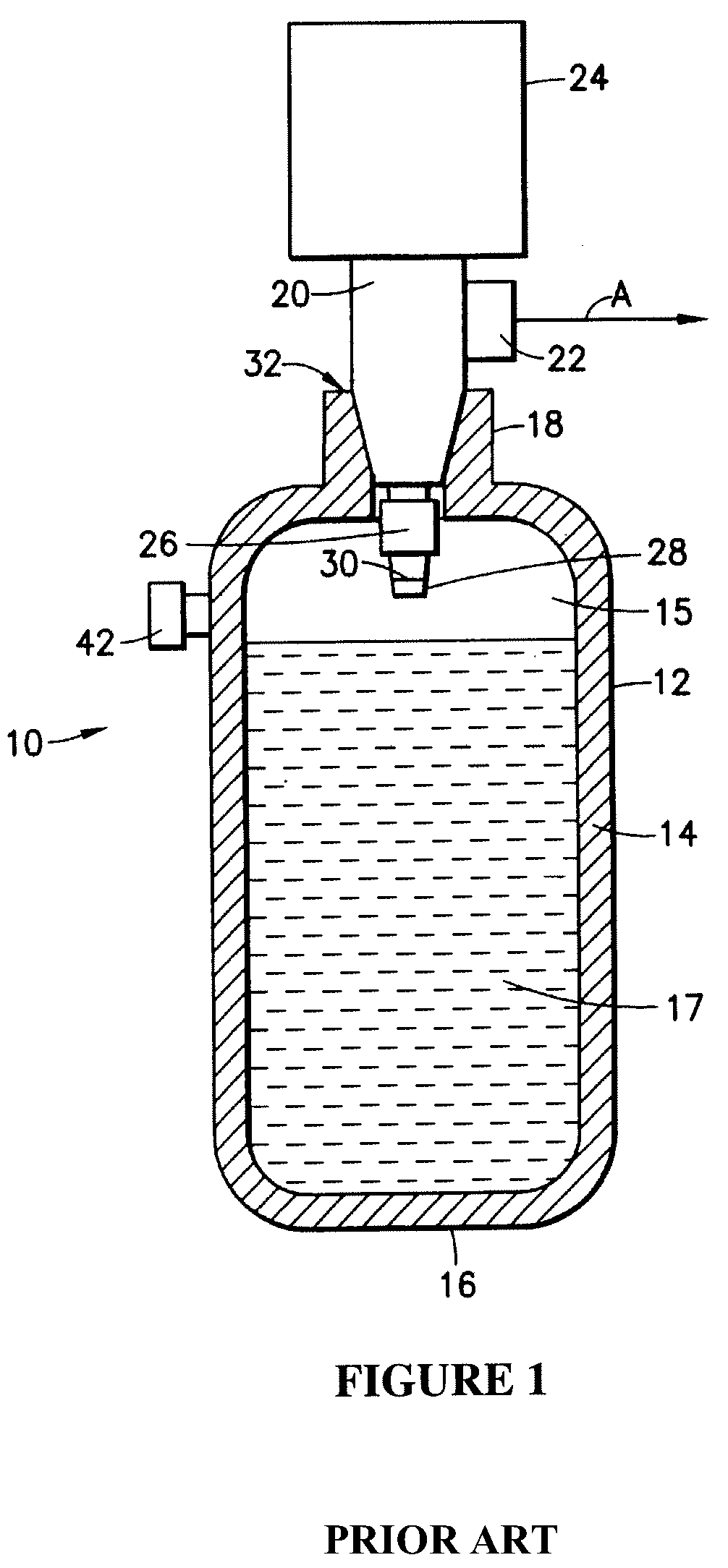
Conventional high pressure gas cylinders are susceptible to leakage from damaged or malfunctioning regulator assemblies, as well as to rupture or other unwanted bulk release of gas from the cylinder if internal decomposition of the gas leads to rapid increasing interior gas pressure in the cylinder.

Method used


Image

  • Apparatus and method for hydrogen generation from gaseous hydride
  • Apparatus and method for hydrogen generation from gaseous hydride
  • Apparatus and method for hydrogen generation from gaseous hydride

Examples


Embodiment Construction

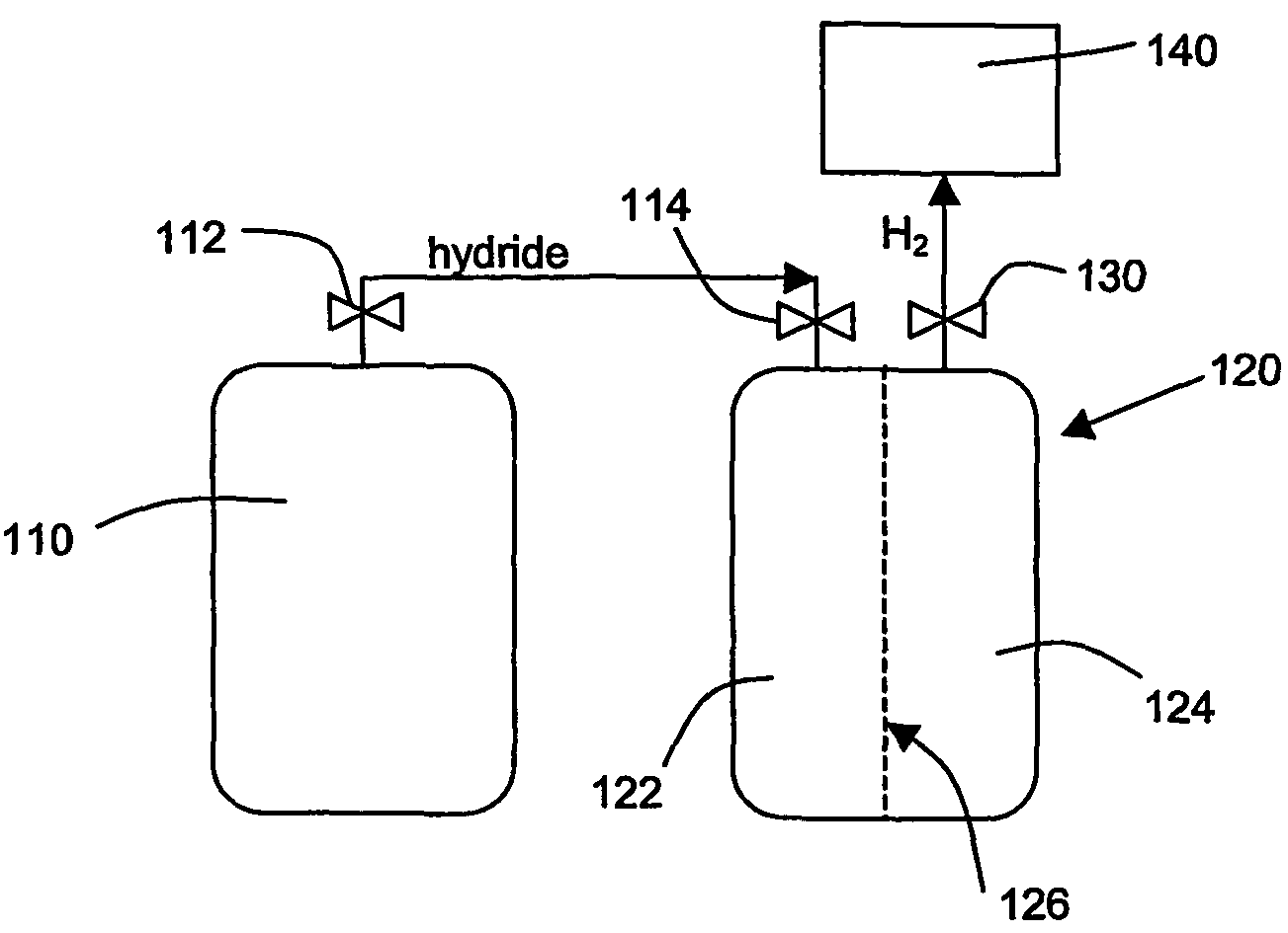
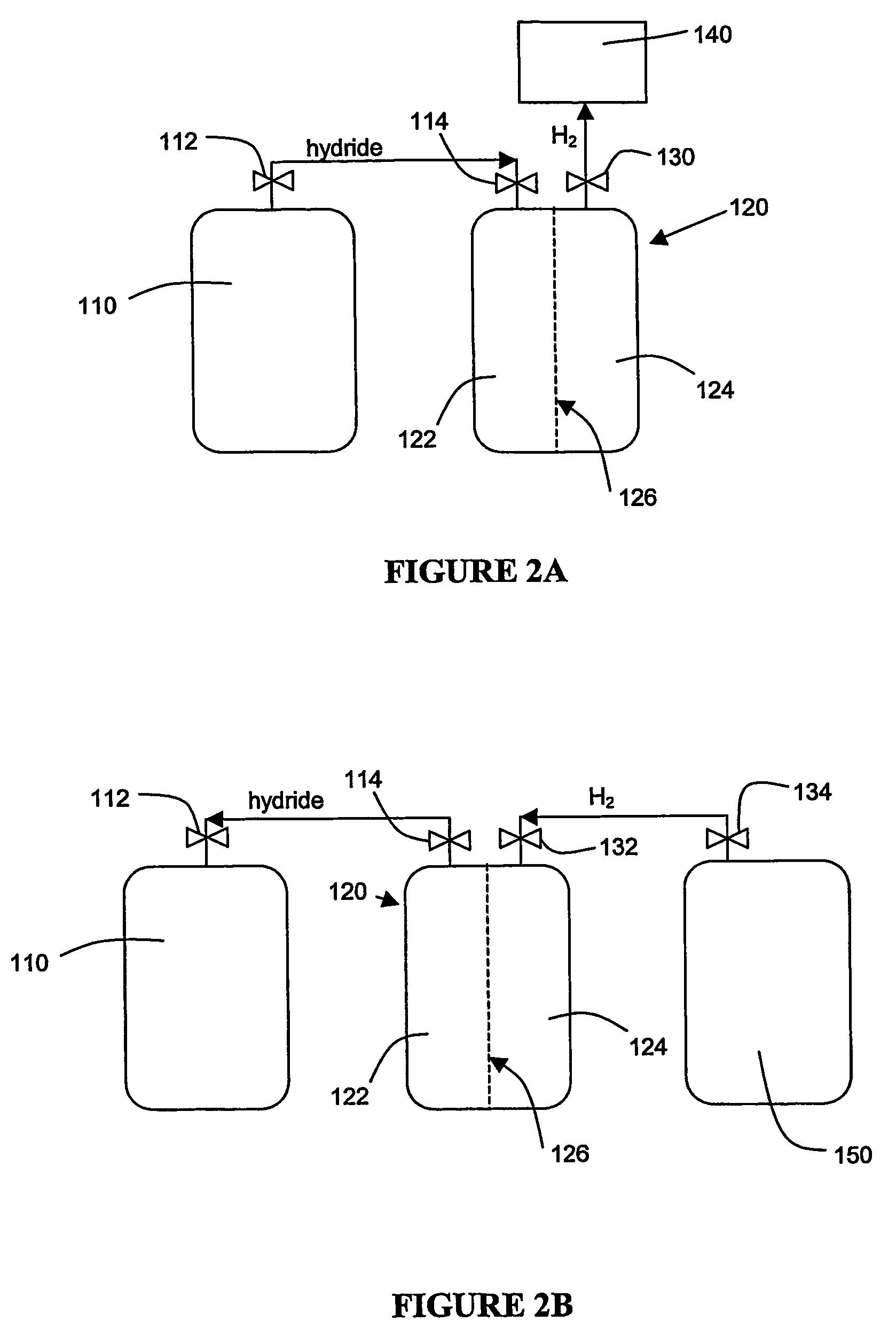
[0043]The instant invention resolves the problem of insufficient hydrogen storage capacity in a vessel or tank, while simultaneously permitting the safe and efficient generation of hydrogen fuel. Specifically, this invention relates to an apparatus and method using storage and dispensing vessels that safely store and dispense gaseous hydrides, and in which the gaseous hydride is decomposed to generate hydrogen gas.

[0044]U.S. Pat. No. 5,528,518, issued May 21, 1996 in the names of Glenn M. Tom and James V. McManus, and U.S. Pat. No. 6,089,027, issued Jul. 18, 2000 in the names of Luping Wang and Glenn M. Tom, are hereby incorporated by reference herein in their entireties.

[0045]The invention provides an alternative to conventional hydrogen storage methods. The invention embodies the following operational aspects:[0046]A. Safe storage of a gaseous hydride material in a reduced pressure vessel; and[0047]B. Decomposition of the gaseous hydride in order to generate H2 according to the fo...


PUM

PropertyMeasurementUnit
pressureaaaaaaaaaa
vapor pressureaaaaaaaaaa

Abstract

An apparatus and method including storage and dispensing vessels to safely store and dispense gaseous hydrides, where the storage and dispensing vessels contain a solid-phase physical sorbent medium having a physically sorptive affinity for gaseous hydrides, and wherein the gaseous hydride is decomposed in the apparatus to generate hydrogen gas. The gaseous hydrides include, but are not limited to, silane, germane, stibine and diborane. The gaseous hydrides decompose spontaneously and / or decomposition is enhanced using surface modified adsorbents. The hydrogen generated by the apparatus may be used in a fuel cell or other hydrogen gas consuming unit.

Description

FIELD OF THE INVENTION[0001]The instant invention relates generally and specifically to solving the problem of insufficient hydrogen storage capacity in a vessel or tank, while simultaneously permitting the safe and efficient generation of hydrogen fuel. Specifically, this invention relates to an apparatus and method using storage and dispensing vessels that safely store and dispense gaseous hydrides wherein the gaseous hydride is decomposed in the apparatus to generate hydrogen gas.BACKGROUND OF THE INVENTION[0002]As the world's population expands, so does the use of carbon-based fuels with a concomitant increase in the amount of carbon dioxide released into the atmosphere. Most now accept that the ever-increasing cumulative amount of atmospheric carbon dioxide is warming the earth's atmosphere, causing climate change. Within the last twenty-five years, there has been a recognition that the global energy system must move steadily away from a reliance on carbon-rich fuels whose comb...

Claims


Application Information

Patent Timeline
Patent Type & Authority Patents(United States)
IPC IPC(8): C01B3/04B01D53/22B01JF17C11/00H01M8/04H01M8/06
CPCB01D53/228C01B3/04C01B6/00F17C11/005H01M8/04208H01M8/04216H01M8/065B01D2257/108C01B2203/066F17C2205/0338F17C2205/0391Y02E60/321Y02E60/364Y02E60/50Y02E60/32Y02E60/36
Inventor CARRUTHERS, J. DONALDARNO, JOSE I.
Owner ADVANCED TECH MATERIALS INC
Learn More