
Color toner

a technology of color toner and toner cartridge, which is applied in the field of color toner, can solve the problems of reducing the yield of toner, reducing the number of resin alternatives, and hardly achieving drastic improvement in low-temperature fixability of toner, and achieves excellent heat-resistant storage stability, low viscosity, and excellent performan

Active Publication Date: 2010-08-17
CANON KK
View PDF5 Cites 14 Cited by
  • Summary
  • Abstract
  • Description
  • Claims
  • Application Information

AI Technical Summary

Benefits of technology

The present invention relates to a color toner for use in a printing machine, copying machine, or facsimile, which forms an image on an electrostatic latent image bearing member and transfers it onto a transfer material to create a final image. The toner needs to have various properties such as high-speed, high-quality image, stability over a long period of time, and low-temperature fixability. The invention aims to improve the properties of the toner by developing a new method for producing spherical toner particles with a small particle size distribution and a high yield, and by using a specific combination of a core and shell for the toner particles to achieve compatibility between low-temperature fixability and other desirable properties such as charging characteristic, heat-resistant storage stability, and heat characteristic.

Problems solved by technology

However, the toner based on a pulverization method involves the following problem: a resin to be used in the toner must be selected from resins each excel lent in heat-resistant storage stability, so the number of resin alternatives is small, and a drastic improvement in low-temperature fixability of the toner is hardly achieved.
Further, the toner involves the following problem: upon sharpening of the particle size distribution of the toner for the acquisition of high developing performance, the yield in which the toner is produced reduces, or an additionally large number of production steps for the toner are needed.
As a result, the following situation may arise: the generation of a fine powder of the order of submicrons, the exposure of a wax, and the embedment of a flowability-imparting agent in the surface of the toner occur, so the quality of an image formed with the toner reduces.
However, each of the above polymerization methods involves the following problem: the binder resin of the toner is limited to a vinyl resin.
However, the method may involve the emergence of a problem similar to that in the case of such pulverized toner as described above because the surface layer of each toner particle is apt to peel from the toner base particle of the particle so as to serve as a fine powder.
When a capsule type toner the core and shell of which are formed of different materials as described above is used in a high-productivity apparatus, the following problem is apt to occur: a surface layer (B) is apt to peel from a toner base particle (A), and the surface layer serves as a fine powder to reduce the durable stability of the toner.

Method used


Image

  • Color toner
  • Color toner
  • Color toner

Examples


example 1

Production of Toner Particles 1

[0394]Prior to the preparation of an aqueous phase, an ultrasonic wave was applied from an ice water-filled ultrasonic dispersing unit (UT-305HS manufactured by Sharp Corporation) to a beaker containing the liquid toner composition 1 at an output of 60% for 5 minutes in order that the wax and the pigment in the liquid toner composition might be loosened.

(Emulsifying and Desolvating Steps)

[0395]

Ion-exchanged water157 parts by mass The dispersion liquid of the resin fine particles 134 parts by mass(4 parts by mass of the resin fineparticles were loaded withrespect to 100 parts by mass of the tonerbase particles (A).)A 50% aqueous solution of sodium dodecyl24 parts by massdiphenyl ether disulfonate(ELEMINOL MON-7 manufactured bySanyo Chemical Industries Ltd.)Ethyl acetate18 parts by mass

[0396]The above materials were loaded into a beaker different from that containing the liquid toner composition, and the mixture was stirred with a TK HOMOMIXER (manufactu...

example 2

[0469]Toner particles were produced in the same manner as in Example 1 except that: the liquid toner composition 4 was used instead of the liquid toner composition 1; the resin fine particles 4 were used instead of the resin fine particles 1; and the amount of the resin fine particles to be loaded was decreased from 4 parts by mass to 3 parts by mass with respect to the toner base particles (A), and the particles were subjected to an external addition treatment in the same manner as in Example 1, whereby Toner 9 was obtained. Table 4 shows the physical properties of Toner 9 and the results of the evaluation of Toner 9 for electrophotographic performance.

[0470]A toner having a relatively small particle diameter was obtained because the liquid toner composition 4 had a slightly higher acid value than that of the liquid toner composition 1, and was more excellent in granulating performance than the liquid toner composition 1. In contrast to the resin fine particles 1, the resin fine pa...

example 3

[0471]Toner particles were produced in the same manner as in Example 1 except that: the liquid toner composition 5 was used instead of the liquid toner composition 1; and the amount of the resin fine particles 1 to be loaded was decreased from 4 parts by mass to 3 parts by mass with respect to the toner base particles (A), and the particles were subjected to an external addition treatment in the same manner as in Example 1, whereby Toner 10 was obtained. Table 4 shows the physical properties of Toner 10 and the results of the evaluation of Toner 10 for electrophotographic performance. The resultant toner had a G′130 of less than 1.0×10² Pa. The toner showed a fixation starting temperature of 90° C., a value at A level, and a peel temperature of 100° C. (at A level); these results mean that the toner exerted excellent low-temperature fixability. Further, the toner showed good heat-resistant storage stability. Hot offset occurred at 170° C., but the toner showed offset resistance at s...


PUM


Abstract

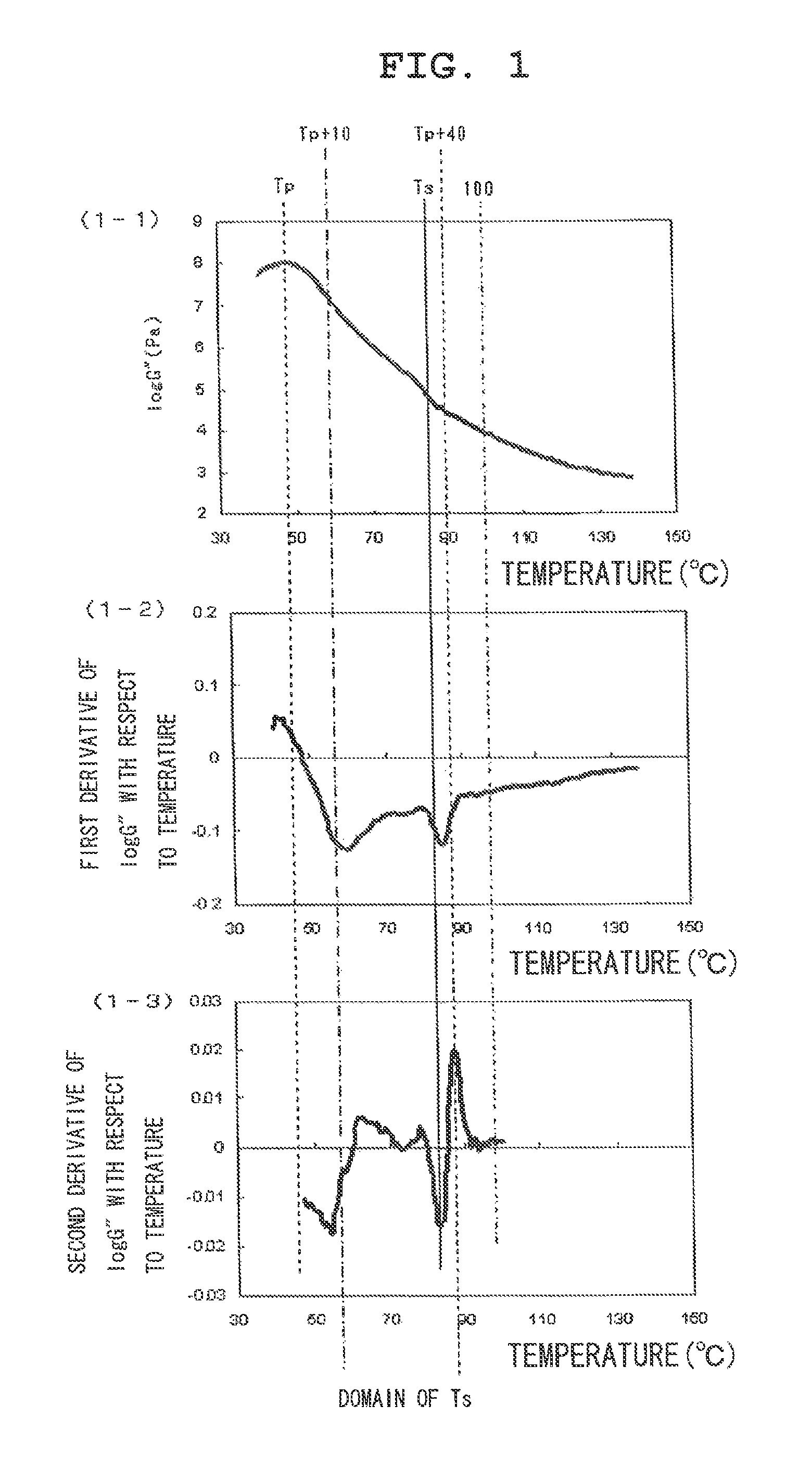
The color toner has capsule type toner particles each having a surface layer (B) mainly formed of a resin (b) on the surface of a toner base particle (A) containing at least a binder resin (a), a colorant, and a wax, in which (1) a temperature Tp at which a curve 1 obtained by plotting a temperature on an axis of abscissa and the common logarithm of a value obtained by dividing the loss modulus G″ of the color toner by the unit of the loss modulus on an axis of ordinate shows a maximum is present, and Tp satisfies the relationship of 40° C.≦Tp≦60° C., (2) a temperature Ts at which a curve 2 obtained by differentiating the curve 1 with respect to the temperature twice shows a local minimum is present in the temperature range of Tp+10(° C.) to Tp+40(° C.), and (3) a ratio G″(Ts) / G″(Ts+5) in the curve 1 is larger than 3.0.

Description

FIELD OF THE INVENTION[0001]The present invention relates to a color toner for use in a recording method employing an electrophotographic method, an electrostatic recording method, or a toner jet system recording method, and more specifically, to a color toner for use in a printing machine, copying machine, printer, or facsimile, which forms a toner image on an electrostatic latent image bearing member in advance, transfers the toner image onto a transfer material to form an image, and fixes the transferred image under heat and pressure to provide an image.BACKGROUND OF THE INVENTION[0002]An electrophotographic method is as described below. A photoconductive substance is utilized so that an electric latent image is formed on an image bearing member (photosensitive member) with various means. Next, a toner image is formed by developing the latent image with toner, and the toner image formed with the toner is transferred onto a transfer material such as paper as required. After that, ...

Claims


Application Information

Patent Timeline
Patent Type & Authority Patents(United States)
IPC IPC(8): G03G9/087G03G9/093
CPCG03G9/0821G03G9/09328G03G9/09371
Inventor TAMURA, SHIGETOKAYA, TAKAAKIFUJITA, RYOICHIKAMBAYASHI, MAKOTO
Owner CANON KK
Learn More