Relational database method for accessing information useful for the manufacture of, to interconnect nodes in, to repair and to maintain product and system units

a relational database and database technology, applied in the field of documenting the construction of assemblies and systems, can solve the problems of restricting the eligibility of mating interfaces for later assembly, and achieve the effect of enhancing the accuracy of the data contained and rapid construction of many different configurations

Inactive Publication Date: 2010-08-10
BCS SOFTWARE LLC
View PDF19 Cites 0 Cited by
  • Summary
  • Abstract
  • Description
  • Claims
  • Application Information

AI Technical Summary

Benefits of technology

[0019]The benefit of having a definition of the reference designated locations in the assembly is that parts may be selected from the parts list and assigned to appropriate locations (where they belong). The benefit of having a definition of the characteristics of a part is that the important characteristics of a part are known and recorded consistently. The benefit of having a definition of the interfaces of a part is that the definition of one interface may be used to select an appropriate mating interface. The existence of these definitions, which only occurs once for each assembly and part, enables the rapid construction of many different configurations of the parts within the assembly. The use of a relational database to perform this process enables the addition of significant error prevention and error detection capabilities to the process, thus enhancing the accuracy of the data contained within the assembly definition. The database also allows reporting of almost any conceivable data analysis.

Problems solved by technology

The definition of the interfaces may restrict the eligibility of mating interfaces for later assembly.

Method used


Image

  • Relational database method for accessing information useful for the manufacture of, to interconnect nodes in, to repair and to maintain product and system units
  • Relational database method for accessing information useful for the manufacture of, to interconnect nodes in, to repair and to maintain product and system units
  • Relational database method for accessing information useful for the manufacture of, to interconnect nodes in, to repair and to maintain product and system units

Examples


Embodiment Construction

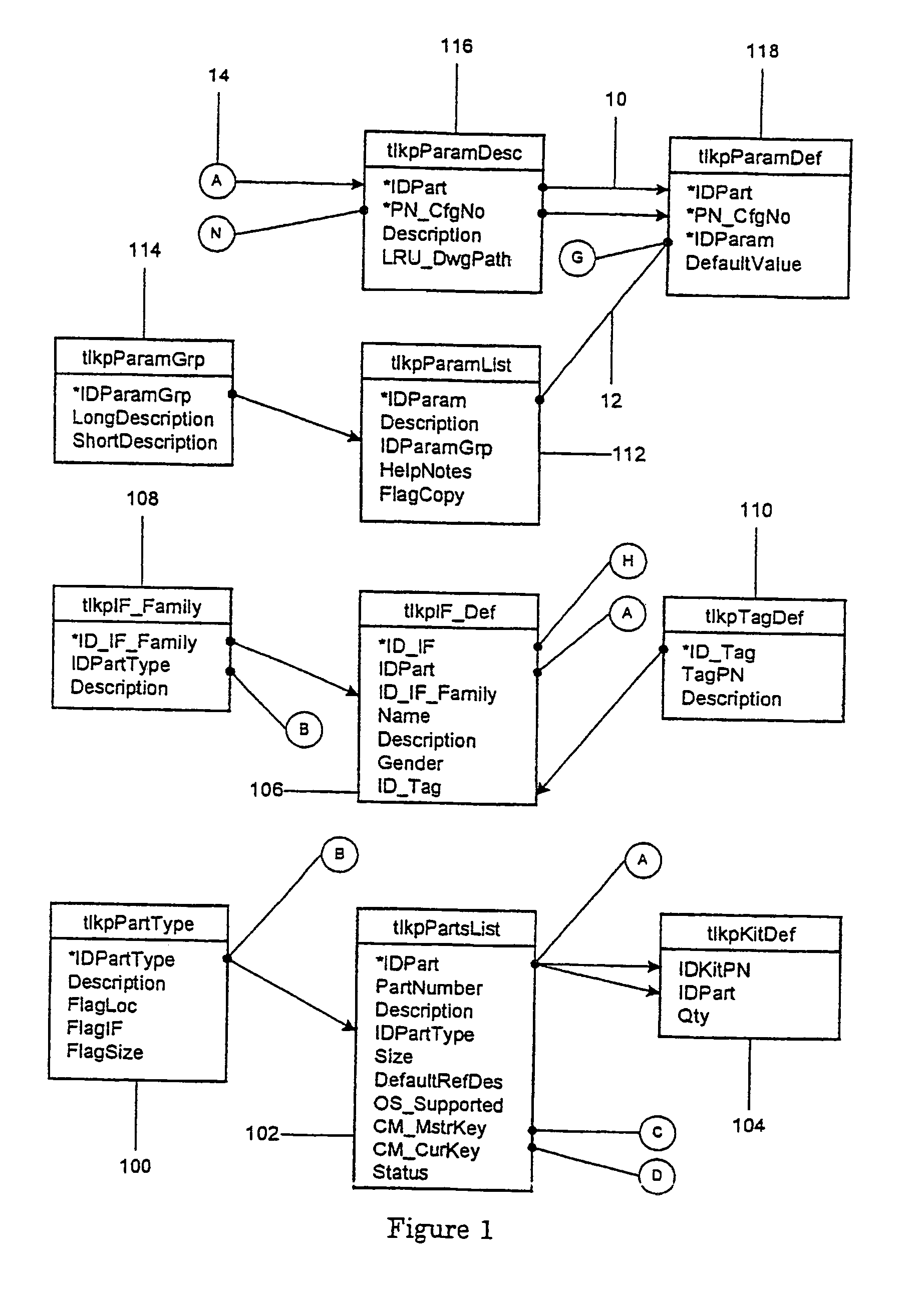
[0034]The embodiment will be presented in the order of the Figures. The Figures show the relational database schema for the part definition, location definition and unit definition respectively. The Figures also show the process for operation of a user interface to the database tables. The description of the process will show how the features of the table schema are used to achieve the intended purpose. The process will not be described in terms of any specific implementation of a user interface since such a user interface will be readily apparent to one skilled in the art. The primary output report of the embodiment will be described.

[0035]Data lookup table tlkpPartType 100 is used to categorize parts and provide control flags that determine which features of the database may or may not apply to each part category. Table I defines the fields of tlkpPartType.

[0036]

TABLE IFields of Table tlkpPartTypeField NameField TypeField Description*IDPartTypeCounterA unique key for each part typ...


PUM


Abstract

A process provides automated coherent documentation of the construction of variably configured assemblies and systems, which consist of mechanical, electrical or electronic subassemblies or components using relational database software. A relational database software program is used to define the location of subassemblies or components within the final assembly or system, define important configuration information for the subassemblies and define the interconnection of the subassemblies within the assembly or system. This process improves upon prior art utilizing schematics, assembly drawings, parts lists and configuration logs based upon ANSI standard documentation practices by reducing the time required to produce such documentation and improving the accuracy of such documentation. The use of a relational database allows for various data manipulations that may be desirable such as error prevention, error detection, data analysis and specified searches.

Description

CROSS-REFERENCE TO RELATED PATENT APPLICATIONS[0001]This is a Continuation application of U.S. patent application Ser. No. 10 / 131,508, that was filed Jun. 11, 2002 now U.S. Pat. No. 6,662,179, and which is a Divisional Application of application Ser. No. 09 / 270,587, now U.S. Pat. No. 6,438,535 that was filed on Mar. 18, 1999 in the names of Scott Jon Benjamin and John Hans Raisanen, which is assigned to Lockheed Martin Corporation.NOTICE OF U.S. GOVERNMENT RIGHTS[0002]The U.S. Government has a paid-up license in this invention, and the right, in limited circumstances, to require the patent owner to license others on reasonable terms as provided by “Contract No. 00024-94-D-5204, awarded by the U.S. Navy.”FIELD OF THE INVENTION[0003]The invention relates generally to documentation of the construction of assemblies and systems and more particularly to the use of relational database software for the automated production of documentation for the construction and support of variably confi...

Claims


Application Information

Patent Timeline
Patent Type & Authority Patents(United States)
IPC IPC(8): G06F17/30G06Q10/10
CPCG06Q10/10Y10S707/99932Y10S707/99933
Inventor BENJAMIN, SCOTT JONRAISANEN, JOHN HANS
Owner BCS SOFTWARE LLC
Why Eureka
Try Eureka