
Real-time self-calibrating sensor system and method

a self-calibration and sensor technology, applied in the field of real-time self-calibration sensor system and method, can solve the problems of inability to accurately measure blood glucose, inherent margins of error,

Active Publication Date: 2010-08-10
MEDTRONIC MIMIMED INC
View PDF133 Cites 57 Cited by
  • Summary
  • Abstract
  • Description
  • Claims
  • Application Information

AI Technical Summary

Benefits of technology

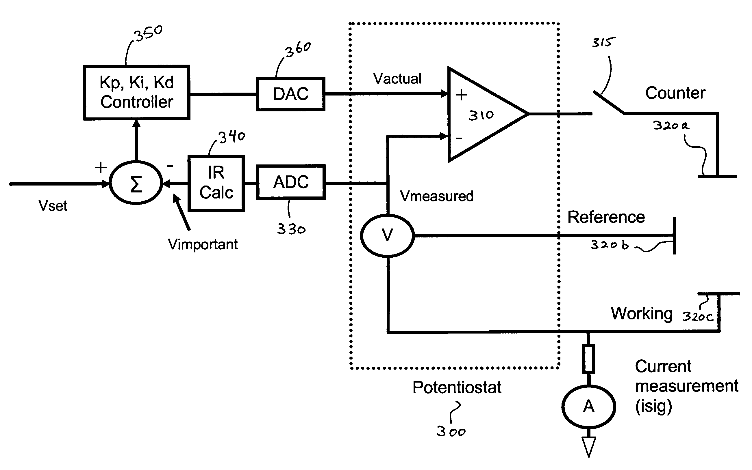
The invention is a system for calibrating a sensor in real time in a characteristic monitoring system. It uses a self-calibration module to determine and compensate for the voltage drop across unwanted resistances in the cell. This is done by a first control unit using a potentiostat to ensure the measured voltage across the sensor's working and reference electrodes is equal to the input voltage, and a second control unit using a PID controller to calculate the value of the unwanted resistance based on the measured voltage. The sensor is then calibrated by calculating the value of the desired voltage across the electrodes, which is the effective amount of potential that drives the electrochemical reaction at the working electrode. This calibration is done on a periodic basis, without the need for external calibration by the user. The invention allows for accurate and efficient calibration of the sensor, improving the accuracy and reliability of the characteristic monitoring system.

Problems solved by technology

Such external calibrations, however, are disadvantageous for various reasons.
For example, blood glucose meters are not perfectly accurate and include inherent margins of error.
Moreover, even if completely accurate, blood glucose meters are susceptible to improper use; for example, if the user has handled candy or other sugar-containing substance immediately prior to performing the finger stick, with some of the sugar sticking to the user's fingers, the blood sugar analysis will result in an inaccurate blood sugar level indication.
Furthermore, there is a cost, not to mention pain and discomfort, associated with each application of the finger stick.

Method used


Image

  • Real-time self-calibrating sensor system and method
  • Real-time self-calibrating sensor system and method
  • Real-time self-calibrating sensor system and method

Examples


Embodiment Construction

[0025]In the following description, reference is made to the accompanying drawings which form a part hereof and which illustrate several embodiments of the present invention. It is understood that other embodiments may be utilized and structural and operational changes may be made without departing from the scope of the present invention.

[0026]The present invention is described below with reference to flowchart illustrations of methods, apparatus, and computer program products. It will be understood that each block of the flowchart illustrations, and combinations of blocks in the flowchart illustrations, can be implemented by computer program instructions. These computer program instructions may be loaded onto a computer or other programmable data processing device (such as a controller, microcontroller, or processor) such that the instructions which execute on the computer or other programmable data processing device will implement the functions specified in the flowchart block or ...


PUM

PropertyMeasurementUnit
conversion timeaaaaaaaaaa
time delayaaaaaaaaaa
voltageaaaaaaaaaa

Abstract

A system and method for calibrating a sensor of a characteristic monitoring system in real time utilizes a self-calibration module for periodic determination of, and compensation for, the IR drop across unwanted resistances in a cell. A current-interrupt switch is used to open the self-calibration module circuit and either measure the IR drop using a high-frequency (MHz) ADC module, or estimate it through linear regression of acquired samples of the voltage across the sensor's working and reference electrodes (Vmeasured) over time. The IR drop is then subtracted from the closed-circuit value of Vmeasured to calculate the overpotential that exists in the cell (Vimportant). Vimportant may be further optimized by subtracting the value of the open-circuit voltage (Voc) across the sensor's working and reference electrodes. The values of Vmeasured and Vimportant are then controlled by respective first and second control units to compensate for the IR drop.

Description

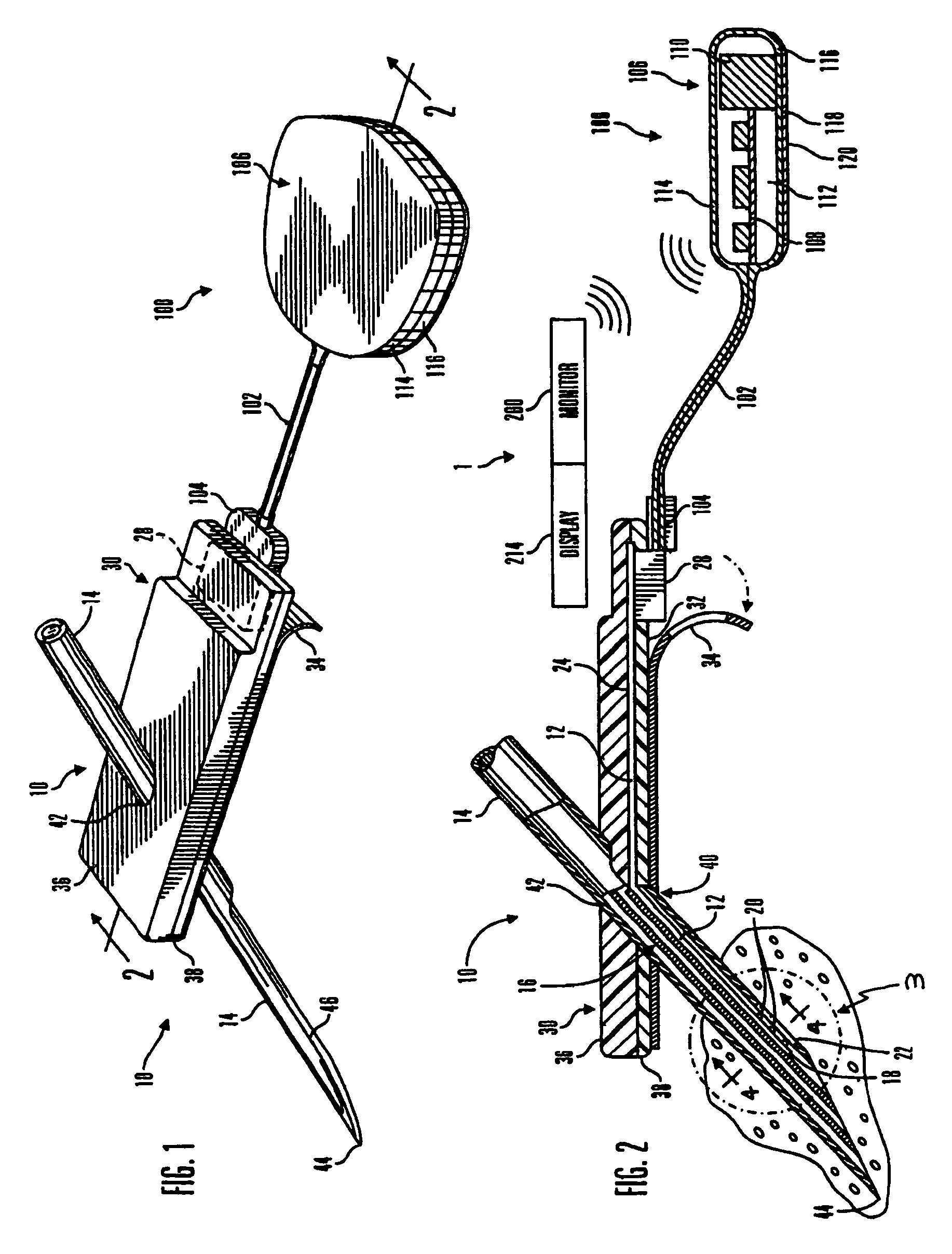
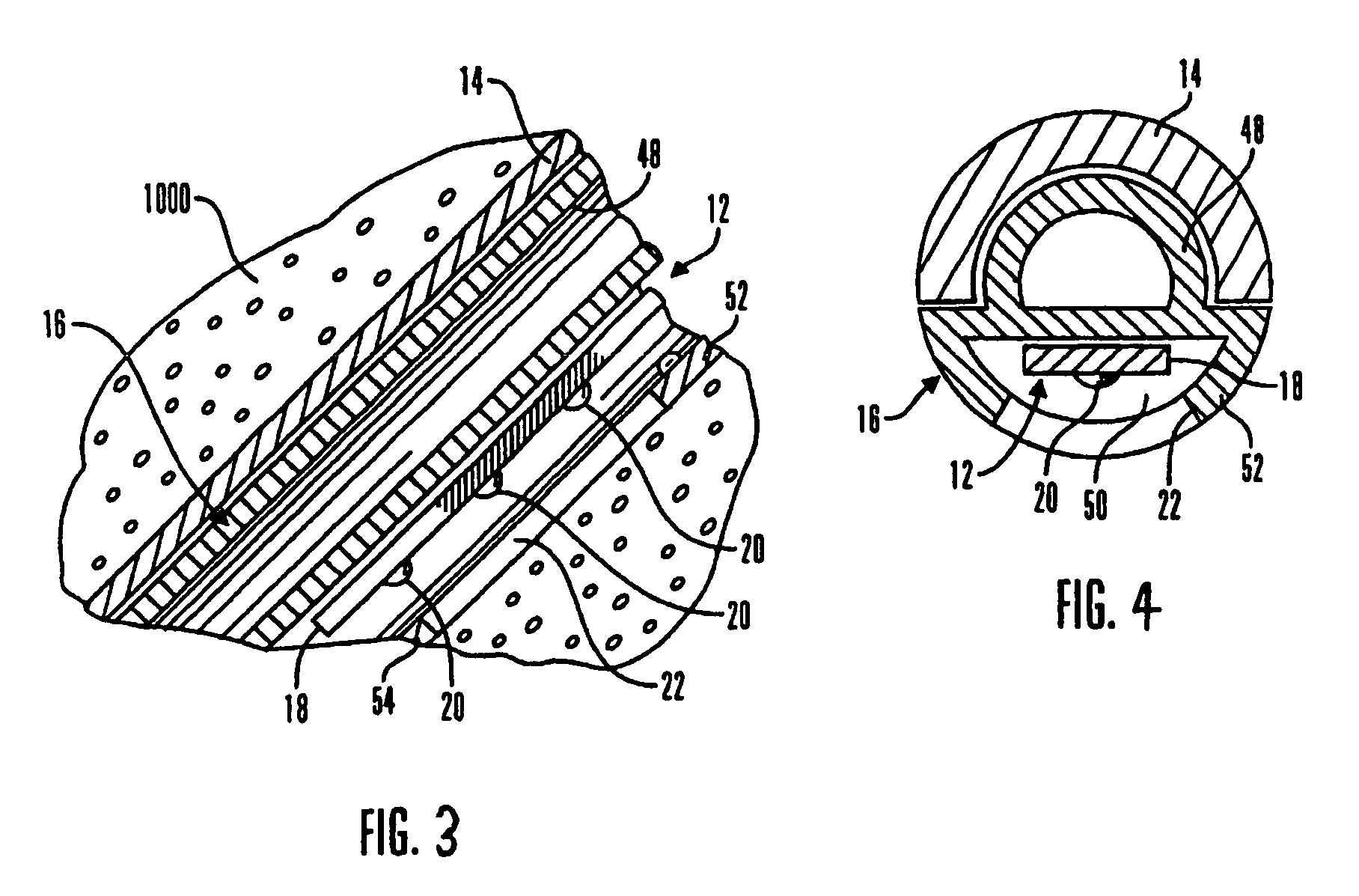
FIELD OF THE INVENTION[0001]This invention relates generally to subcutaneous and implantable sensor devices and, in particular embodiments, to methods and systems for providing real-time self-calibrating sensor devices.BACKGROUND OF THE INVENTION[0002]Over the years, a variety of electrochemical sensors have been developed for detecting and / or quantifying specific agents or compositions in a patient's blood. For instance, glucose sensors have been developed for use in obtaining an indication of blood glucose levels in a diabetic patient. Such readings are useful in monitoring and / or adjusting a treatment regimen which typically includes the regular administration of insulin to the patient.[0003]Generally, small and flexible electrochemical sensors can be used to obtain periodic readings over an extended period of time. In one form, flexible subcutaneous sensors are constructed in accordance with thin film mask techniques in which an elongated sensor includes thin film conductive ele...

Claims


Application Information

Patent Timeline
Patent Type & Authority Patents(United States)
IPC IPC(8): A61B5/05A61B5/00G01N33/50G01N33/487
CPCA61B5/1495A61B5/14865A61B5/1468A61B5/1473A61B5/0031A61B5/14532A61M2005/1726A61B2560/0223
Inventor WANG, LUSHAH, RAJIVMORGAN, WAYNE A.KEENAN, BARRY
Owner MEDTRONIC MIMIMED INC
Learn More